 SpesML Plugin - Technical Viewpoint
Overview
The technical view, as an instance of the technical viewpoint, is the last step on the way to platform-specific models. Here, technical elements finally represent the system for specific platforms while logical components of platform-independent models of the logical view can be mapped to software elements deployed on execution units of these specific platforms. This is needed to generate code out of the models and enable further system engineering activities including software element (“task”) optimization and scheduling.
For a better understanding of the concept of the technical viewpoint, please have a look at the respective theoretical concept documentation. In the mentioned concept documentation we also define specific well-formedness rules for the technical viewpoint. All of them were integrated into the SpesML plugin via MagicDraw validation rules and will be checked each time the validation suite is executed to inform the user whether something in the current technical view model is not correct. In addition, the plugin is implemented in a way that prevents the user to model incorrectly within the technical view (in most cases). In the following, we will explain the implementation of the technical viewpoint within our SpesML plugin.
Method
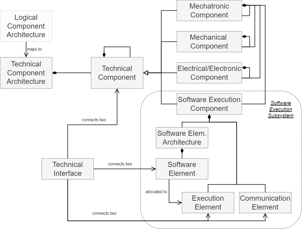
Within the technical view it is possible to model technical architectures. Technical architectures can be composed of various component types to represent the technical specifications of a system (see Figure 1). Logical components of the logical view can then be mapped onto these technical components. A technical architecture can not only represent mechanical, electrical/electronic, or mechatronic elements (or any generic technical element) but also a software execution subsystem. A software execution subsystem is a model of the pure software part of the system including its execution elements. It contains a software element architecture with software elements, often called tasks, onto which the software-relevant logical (sub-)components of the logical view are mapped. Furthermore, it models the execution hardware topology with execution units like ECUs and communication elements like buses. An allocation of software elements to execution units realizes the final deployment.
Regarding the development process, one step is to create the technical representation of the system with all available components of the technical viewpoint (as far as needed). This should include at least one software execution subsystem. Modeling such a software execution subsystem with all its software elements and execution units is another step. Since the logical architecture should be mapped to the technical architecture, we already recommended building the logical and now the technical architecture in a way that a 1:1 mapping is possible between logical and technical components, but this is only a recommendation. In addition, it simplifies the process when already in the logical view the pure software-related logical components are separated from the other logical components. Then, it is easy to map them directly to a technical component representing the software execution subsystem and internally to the defined software elements. However, we do not force a 1:1 mapping and it is also very usual that some technical components exist that do not have a match within the logical architecture, because they were not needed for a platform-independent model, but still contribute to the technical representation of an actual platform. After mapping logical to technical components (including the software elements), the final deployment needs to be done by mapping the software elements to the modeled execution units. It should be said that the development is not a strict step-by-step process, but is usually done by building the technical architecture with technical components and elements of the software execution subsystem while creating in parallel the traces between logical and technical view and the allocation within the technical view regarding the deployment.
We recommend that the software execution subsystem is modeled on a separate (lower) granularity level (see theoretical concept). How to create a new granularity level is described here. However, we also allow in the tool plugin that the internal software execution subsystem with its software elements and execution elements can be modeled on the same level (just hierarchical), i.e., in the same MagicDraw project directly inside the Software Execution Component.
Structure
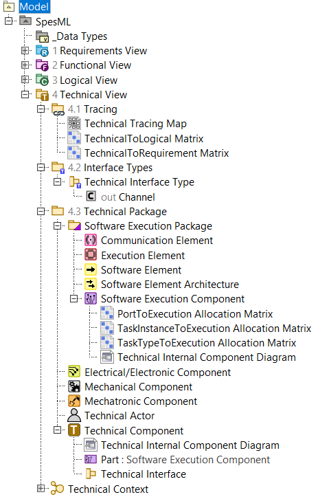
The SpesML plugin has a separate folder for the technical view, called Technical View (see Figure 2). Within this folder, it is possible to create folders for technical components (Technical Package), for technical interfaces types (Technical Interface Types Package), and for technical tracing (Technical Tracing Package). Inside a Technical Tracing Package, all tracing diagrams can be created: Technical Tracing Map, TechnicalToLogical Matrix, and TechnicalToRequirement Matrix. Inside a Technical Interface Types Package, all possible interface types can be created that are usable for the interfaces between technical elements (see Technical Interface).
Inside a Technical Package, other Technical Packages can be created for better organization, but more important are the possibilities of the component creations. The generic Technical Component can be used for everything. If something more specific is needed, then the Mechanical, Electrical/Electronic or Mechatronic Components are available. In addition, the modeler can define a Technical Context inside a Technical Package. The Technical Context behaves like a Technical Component, but can already be placed in the top level of the Technical View folder to create a starting point for the system and a possibility to represent the connected external systems and Technical Actors, which can be created in a Technical Package as well. To indicate that a component is representing an external (sub-)system, the corresponding part property External can be set to Yes (under the element properties/tags).
What is still missing is the software execution subsystem. For better guidance and separation, it is only possible to create first a Software Execution Package inside a Technical Package. Within a Software Execution Package, the modeler can then create Software Execution Components, which are the containers for everything of a software execution subsystem. A Software Execution Package can also contain Software Element Architectures and Software Elements, as well as Execution Elements and Communication Elements. In our concept description, we are mentioning execution platforms. Such an element type does not exist explicitly in the plugin implementation since the Software Execution Component can directly contain platform elements like the Execution Element and Communication Element in its Technical Internal Component Diagram to represent the topology of the execution platform.
Every component (and the Technical Context) can have its own Technical Internal Component Diagram where its containing elements are represented. Depending on the owner of the diagram, only some internal components can be placed in the diagram:
- The Technical Component as well as the Technical Context can contain Technical, Mechanical, Electrical/Electronic, Mechatronic, and Software Execution Components.
- Mechatronic Components can contain Mechatronic, Mechanical, Electrical/Electronic, and Software Execution Components.
- Mechanical and Electrical/Electronic Components can only contain internal components of their own type.
- Software Execution Components can contain Software Element Architectures, Execution Elements and Communication Elements.
- Software Element Architectures can contain Software Elements.
No behavior is modeled inside the technical view, which is why the composition of the components inside the (nested) diagrams is the main part of the technical view, together with the component tracing and the allocation of Software Elements to Execution Elements for the deployment.
To connect this composition of technical elements, it is possible to place interfaces (proxy ports) on every element and connect them with a Connector if both ports have the same interface type (defined in a Technical Interface Types Package). All elements can be connected via a generic Technical Interface, which is defined by its Technical Interface Type. Technical Interface Types can have Channels, which are inherited from the Universal Interface Model. Therefore it is possible to represent/model communication flows between technical elements. An exception is the Software Element Architecture because it does not make sense to connect Software Elements in Software Element Architectures with the physical elements outside of Software Element Architectures, which is why Software Element Architectures cannot be connected in any way with other elements. However, the Software Elements themselves inside Software Element Architecture can be connected among each other again with Technical Interfaces.
To trace logical components to technical components or actually the other way around, you can create and fill a TechnicalToLogical Matrix inside the Technical Tracing Package. The same goes for technical components to requirements with a TechnicalToRequirement Matrix.
Regarding the deployment, it is possible to create allocation matrices for a Software Execution Component (similar to a Technical Internal Component Diagram). These allocation matrices can only be added directly to a Software Execution Component (like adding a diagram to it) and not anywhere else. You can create a TaskInstanceToExecution Allocation Matrix if you want to allocate Software Element instances to Execution Element instances, i.e., modeling the deployment of Software Elements to Execution Elements. The same can be done with a TaskTypeToExecution Allocation Matrix, but now you do not use instances but defined types of these elements. To allocate then Software Element ports to Execution Component ports, you can use a PortToExecution Allocation Matrix.
How to model
TODO: Should be done if the technical viewpoint is completely realized in the plugin (and in a final state).
Elements
/Technical View
This element is a UML/SysML Package with a dedicated stereotype that allows defining an adequate SpesML model structure and guides users by restricting what elements and diagrams can be created below this package for the technical view. This package contains only further packages to separate different purpose categories within the technical view. In addition, it is already possible to create a Technical Context as a starting point.
 /Technical Tracing Package
This element is a UML/SysML Package with a dedicated stereotype that allows defining an adequate SpesML model structure and guides users by restricting what elements and diagrams can be created below this package for the technical view. This package contains only tracing-related relation maps and matrixes.
 /Technical Interface Types Package
This element is a UML/SysML Package with a dedicated stereotype that allows defining an adequate SpesML model structure and guides users by restricting what elements and diagrams can be created below this package for the technical view. This package contains only interface types that can be used for Technical Interfaces.
 /Technical Package
This element is a UML/SysML Package with a dedicated stereotype that allows defining an adequate SpesML model structure and guides users by restricting what elements and diagrams can be created below this package for the technical view. This package contains only standard technical components like Technical, Mechanical, Electrical/Electronic and Mechatronic Components, and context-related elements like Technical Contexts and Technical Actors. In addition, it can also contain the more specialized Software Execution Package, which is the entry point for software execution subsystem elements.
 /Software Execution Package
This element is a UML/SysML Package with a dedicated stereotype that allows defining an adequate SpesML model structure and guides users by restricting what elements and diagrams can be created below this package for the technical view. This package contains only elements regarding the software execution subsystem. It includes Software Execution Components, Software Element Architectures, Software Elements, Execution Elements and Communication Elements.
 /Technical Context
The Technical Context is a separate element but it mainly behaves as a standard Technical Component like containing a Technical Internal Component Diagram. Its purpose is to act as a starting point for the system model, where the system under development is represented as only one component, usually a Technical Component, and the connected external systems and Technical Actors can be modeled to show the environment/context of the system under development. A component can be defined as external by changing the property External of this component from No to Yes. Another property is System under development with which the modeler can specify if a component is the current system under development or not (the latter is the default). To support the purpose as starting point and initial overview, the Technical Context is the only element (besides packages) that can be directly placed in the top Technical View folder. If a user opens the technical view, it will directly see the Technical Context element and can open it to see first the context and then go deeper into the system under development.
 /Technical Actor
This element is based on a SysML Block with a dedicated stereotype that allows defining where the element can be placed and other specifications. In addition, it restricts that only certain sub-elements can be created below it. In the case of the Technical Actor, it prevents the creation of any sub-element below it including any diagram except Technical Interfaces. The Technical Actor just indicates an actor that has a connection to the system under development without any further modeling of this actor. Therefore, the Technical Actor makes in most cases only sense to be placed in the Technical Context. To model the connections with the system under development, it is possible to add Technical Interfaces to the Technical Actor and connect them with Technical Interfaces of other components, usually, the one representing the system under development.
 /Technical Component
This element is based on a SysML Block with a dedicated stereotype that allows defining where the element can be placed and other specifications. In addition, it restricts that only certain sub-elements can be created below it. A Technical Component is a generic component and can represent everything. It can be used as a placeholder and if it is not needed to specify the modeled element further or if it is a container for components of different disciplines. A Technical Component can be further specified by adding a Technical Internal Component Diagram to it. With such an owner it is possible to place further Technical, Mechanical, Electrical/Electronic, Mechatronic and Software Execution Components in this diagram. A Technical Component can provide a syntactic interface via Technical Interfaces, which can be used to connect this component to other components to model just the composition or to model actual information flow if the used Technical Interface Type contains Channels.
 /Mechanical Component
This element is based on a SysML Block with a dedicated stereotype that allows defining where the element can be placed and other specifications. In addition, it restricts that only certain sub-elements can be created below it. A Mechanical Component is a specific component of the mechanical engineering discipline. It can be used to model mechanical parts of the system, like e.g., the mechanical presence of a door or a motor shaft. A Mechanical Component can be further specified by adding a Technical Internal Component Diagram to it. With such an owner it is possible to place further Mechanical Components in this diagram. A Mechanical Component can provide a syntactic interface via Technical Interfaces, which can be used to connect this component to other components to model just the composition or to model actual information flow if the used Technical Interface Type contains Channels.
 /Mechatronic Component
This element is based on a SysML Block with a dedicated stereotype that allows defining where the element can be placed and other specifications. In addition, it restricts that only certain sub-elements can be created below it. A Mechatronic Component is a specific fusion component of mainly the mechanical and electrical engineering disciplines. It can be used to model parts of the system that have mechanical as well as electrical shares, like e.g., an electrical motor. Software can also be part of it. A Mechatronic Component can be further specified by adding a Technical Internal Component Diagram to it. With such an owner it is possible to place Mechanical, Electrical/Electronic, and further Mechatronic Components in this diagram, as well as Software Execution Components. A Mechatronic Component can provide a syntactic interface via Technical Interfaces, which can be used to connect this component to other components to model just the composition or to model actual information flow if the used Technical Interface Type contains Channels.
 /Electrical/Electronic Component
This element is based on a SysML Block with a dedicated stereotype that allows defining where the element can be placed and other specifications. In addition, it restricts that only certain sub-elements can be created below it. An Electrical/Electronic (E/E) Component is a specific component of the electrical engineering discipline. It can be used to model E/E parts of the system, like e.g., a light or a sensor. An Electrical/Electronic Component can be further specified by adding a Technical Internal Component Diagram to it. With such an owner it is possible to place further Electrical/Electronic Components in this diagram. An Electrical/Electronic Component can provide a syntactic interface via Technical Interfaces, which can be used to connect this component to other components to model just the composition or to model actual information flow if the used Technical Interface Type contains Channels.
 /Software Execution Component
This element is based on a SysML Block with a dedicated stereotype that allows defining where the element can be placed and other specifications. In addition, it restricts that only certain sub-elements can be created below it. A Software Execution Component is a container representing the software execution subsystem (see concept). It is used by the software engineering discipline to model the software part of the system (and its execution environment). A Software Execution Component can be further specified by adding a Technical Internal Component Diagram to it. With such an owner it is possible to place mainly Execution and Communication Elements in this diagram, but also Software Element Architectures if wanted. In this implementation, we have simplified the structure of a Software Execution Component and directly allow the placing of Execution and Communication Elements in its diagram without adding an additional container for them in form of a execution platform. Therefore, the Software Execution Component directly represent the execution environment (its topology). A Software Execution Component can provide a syntactic interface via Technical Interfaces, which can be used to connect this component to other components to model just the composition or to model actual information flow if the used Technical Interface Type contains Channels.
 /Execution Element
This element is based on a SysML Block with a dedicated stereotype that allows defining where the element can be placed and other specifications. In addition, it restricts that only certain sub-elements can be created below it. An Execution Element is a specific (atomic) element of the software execution subsystem that represents an execution unit, like an ECU, on which Software Elements can be deployed and executed. An Execution Element cannot be further specified by adding a diagram to it. It is an atomic unit to which Software Elements can be allocated to realize the (software) deployment. An Execution Element can provide a syntactic interface via Technical Interfaces, which can be used to connect this element to other elements, in this case other Execution Elements or Communication Elements to model just the composition or to model actual information flow if the used Technical Interface Type contains Channels.
 /Communication Element
This element is based on a SysML Block with a dedicated stereotype that allows defining where the element can be placed and other specifications. In addition, it restricts that only certain sub-elements can be created below it. A Communication Element is a specific (atomic) element of the software execution subsystem that represents a communication unit, like a CAN bus, connecting Execution Elements. However, it is not needed to have always specifically modeled Communication Elements between Execution Elements. A Communication Element cannot be further specified by adding a diagram to it. It is an atomic unit that can mainly be used to indicate/model communication elements between Execution Elements (if wanted). A Communication Element can provide a syntactic interface via Technical Interfaces, which can be used to connect this element to other elements, in this case Execution Elements to model just the composition or to model actual information flow if the used Technical Interface Type contains Channels.
 /Software Element Architecture
This element is based on a SysML Block with a dedicated stereotype that allows defining where the element can be placed and other specifications. In addition, it restricts that only certain sub-elements can be created below it. A Software Element Architecture is a container element for Software Elements to represent the software part of a software execution subsystem (represented by Software Execution Component). A Software Element Architecture can be further specified by adding a Technical Internal Component Diagram to it. With such an owner it is possible to place Software Elements in this diagram. A Software Element Architecture does NOT provide any syntactic interface via e.g., Technical Interfaces. It is only used as a virtual container for all the Software Elements and does not need to have any connection with other (physical) elements.
 /Software Element
This element is based on a SysML Block with a dedicated stereotype that allows defining where the element can be placed and other specifications. In addition, it restricts that only certain sub-elements can be created below it. A Software Element is a specific (atomic) element representing a single software element like a task that was traced from the logical view and should be executed on an execution unit represented by an Execution Element. A Software Element cannot be further specified by adding a diagram to it. It is an atomic unit to which software-related Logical Components of the logical viewpoint can be traced, and which itself can then be allocated to Execution Elements to realize the final (software) deployment with such an allocation. A Software Element can provide a syntactic interface via Technical Interfaces, which can be used to connect this element to other elements, in this case, other Software Elements (to model actual information flow if the used Technical Interface Type contains Channels).
 /Technical Interface
This element is based on a SysML Proxy Port with a dedicated stereotype that allows defining where the element can be placed and other specifications. A Technical Interface is used to connect different technical elements/components generically. It can be specified further by using Technical Interface Types and Channels to model the connection between the elements and even actual information flows (via the channels). A Technical Interface is nothing else than a port that can be placed on a technical element. If another technical element has also such a port/interface with the same Technical Interface Type, the user can connect these two ports with a Connector line.
 /Technical Interface Type
This element is based on a SysML Interface Block with a dedicated stereotype that allows defining where the element can be placed and other specifications. A Technical Interface Type is used to specify the type of a Technical Interface. It needs to be defined separately in a Technical Interface Types Package and can then be used to fill the Type property of a Technical Interface. A Technical Interface Type can either contain a Value Property (e.g., a specific enumeration) or a Channel (or multiple ones).
 /Channel
This element is based on a SysML Flow Property with a dedicated stereotype that allows for defining the flow direction and other specifications. Its concept is explained in the Universal Interface Model. It can be added as an element to a Technical Interface Type. Channels enable signal/information transport between elements that are connected with an interface connection that has such an interface type (with a channel). A channel has a type (the type of the transported signal/information), which can be any pre-defined basic data type or a new user-defined data type (see Data Types).
Diagrams
 /SpesML Technical Tracing Map
This relation map shows technical elements like Technical Components, Mechanical Components, etc. and to what Requirements, Functional Component or Logical Components these elements are tracing to. By default, all technical elements are shown but it is also possible to drag & drop a single technical element to the relation map to show only the particular relationships.
 /SpesML TechnicalToLogical Matrix
This matrix allows to create relationships between elements of the technical view and elements of the logical view.
/SpesML TechnicalToRequirement Matrix
This matrix allows to create relationships between elements of the technical view and requirement view.
 /SpesML Technical Internal Component Diagram
This diagram is based on a UML Composite Structure Diagram/SysML Internal Block Diagram and provides a reduced diagram toolbar related to SpesML for the technical view. Note that intentionally any technical element cannot be created using the diagram toolbar. Instead, it is recommended to create these elements by dragging/dropping a technical element into the diagram. Depending on the owner of the diagram, only certain elements are allowed to be placed in this diagram. For example, for a Technical Internal Component Diagram of a Mechanical Component, it is only allowed to place further Mechanical Component, for a Technical Internal Component Diagram of a Software Execution Component it is only allowed to place Execution Elements and Communication Elements, etc. If you drag and drop a wrong element inside a diagram, you will get a warning message that will tell you which elements are allowed for this specific diagram.
/SpesML TaskInstanceToExecution Allocation Matrix
This matrix allows to create relationships between Software Elements in Software Element Architectures and Execution Elements in Software Execution Components. This creates an allocation between Software Elements and Execution Elements that represents the deployment of these software elements on these execution units. All of this happens on the instance level, meaning that every instance/part of a Software Element and an Execution Element can be allocated separately. To use this matrix, a scope needs to be set (above the matrix diagram). As the description at the bottom of the matrix diagrams indicates, the row scope should be the Software Element Architecture of the wanted Software Elements and the column scope the Software Execution Component of the wanted Execution Element.
/SpesML TaskTypeToExecution Allocation Matrix
This matrix allows to create relationships between Software Elements in Software Element Architectures and Execution Elements in Software Execution Components. This creates an allocation between Software Elements and Execution Elements that represents the deployment of these software elements on these execution units. All of this happens on the type level, meaning that only the defined types/blocks of a Software Element and an Execution Element can be allocated (instances of them cannot be allocated separately!). To use this matrix, a scope needs to be set (above the matrix diagram). As the description at the bottom of the matrix diagrams indicates, the row scope should be the package in which the wanted Software Elements are defined, and the column scope the package in which the wanted Execution Elements are defined.
/SpesML PortToExecution Allocation Matrix
This matrix allows to create relationships between Technical Interfaces (ports) of Software Elements in Software Element Architectures and Technical Interfaces (ports) of Execution Elements in Software Execution Components. This creates an allocation between Software Element ports and Execution Element ports, which supports the deployment of these software elements on these execution units. To use this matrix, a scope needs to be set (above the matrix diagram). As the description at the bottom of the matrix diagrams indicates, the row scope should be the package in which the wanted Software Elements ports are defined, and the column scope is the package in which the wanted Execution Element ports are defined. The port allocation is only needed on the type level because together with a TaskInstanceToExecution Allocation Matrix, it is then always possible to know which port instances (depending on the Software Element and Execution Element instance) are meant to be allocated.