 SpesML Plugin - Functional Viewpoint
Overview
The Functional Viewpoint contains three model types that can be used to describe the desired functionality of a system on a system level (i.e., primarily from the perspective of external actors such as users or external systems).
In the center of the Functional Viewpoint is the concept of system functions. A system function describes a coherent set of interactions between a system and its external actors. The granularity of a system function is comparable to that of a Use Case. A system with several system functions can be called a multifunctional system. In general, system functions describe system behavior, which is largely independent of each other, however, system functions may also influence each other in specific cases. In the Functional Viewpoint, these influences are modeled by so-called mode channels between system functions.
The Functional Viewpoint then consists of three model types:
- Functional Black-box Model: Contains all system functions and structures them in a hierarchy
- Functional White-box Model: Describes the decomposition of one particular system function into a set of related white-box functions
- Mode Model: Describes operational states of the system. These operational states can be referenced in mode channels that describe dependencies between system functions.
Method
System functions structure and formalize the functional requirements of a system. An engineer can either start from existing functional requirements and structure them according to system functions or, start from a set of desired system functions and then specify detailed requirements for them. In a second step, the engineer may decompose system functions into a set of connected white-box functions to assign smaller units of functionality to logical components that satisfy the functionality specified by a white-box function. Besides specifying system functions, an engineer can also specify distinct modes of operations that a system may be in (called system modes). System modes can be influenced by behavior specified in system functions. On the other hand, a change in a system mode can also influence the behavior of system functions.
The following figure illustrates these relations: 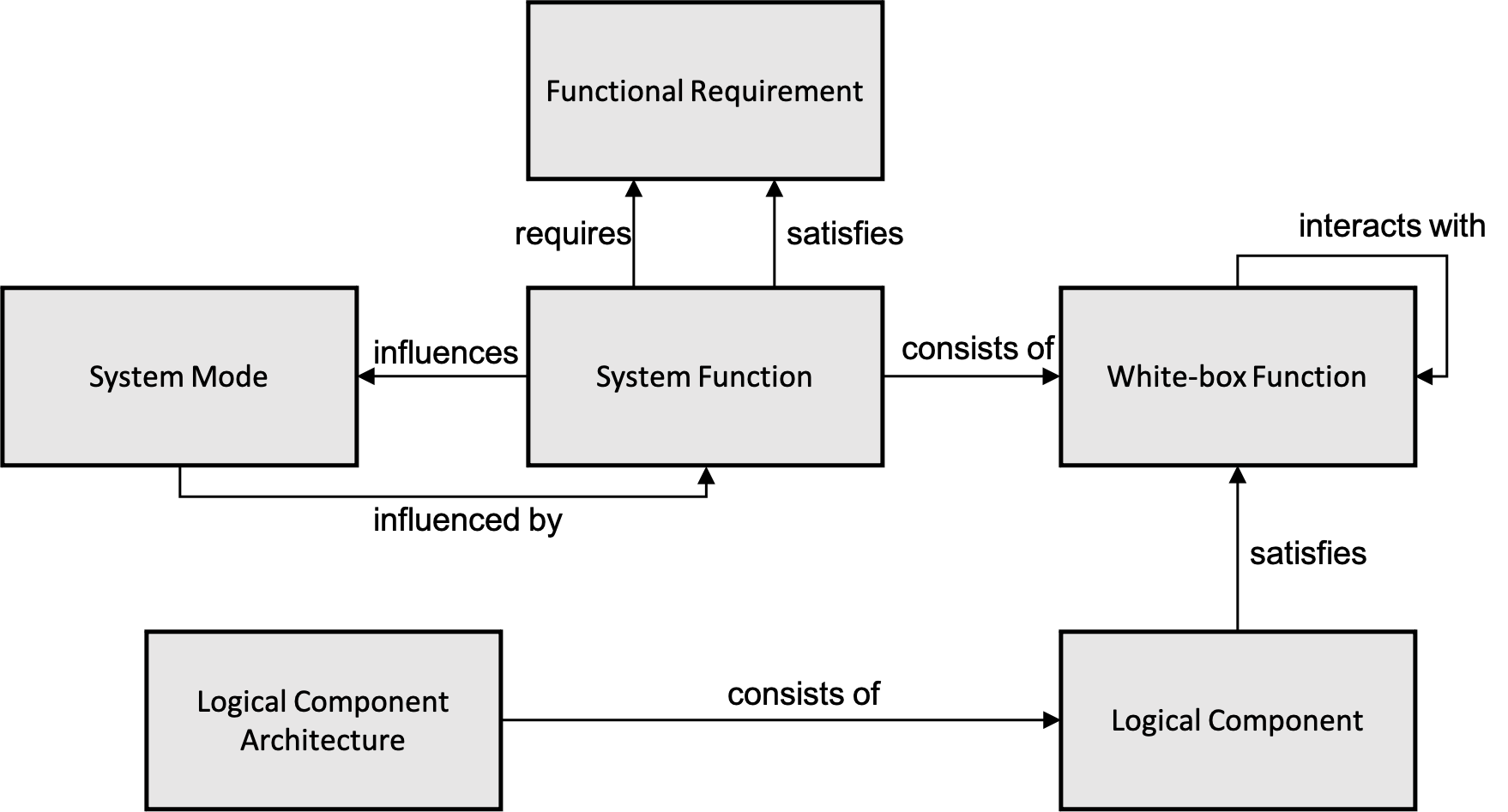
Structure
The different models of the Functional Viewpoint create a functional view of a system that is structured in the Containment Tree of a project. A top-level node called FunctionalView contains all elements of this view (see figure below).
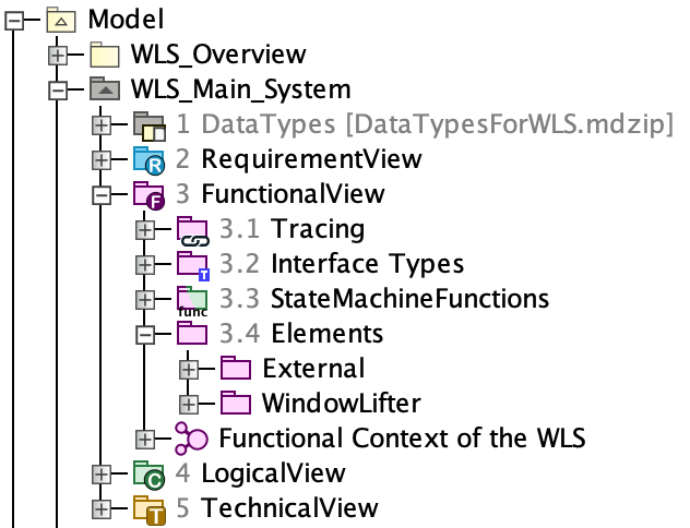
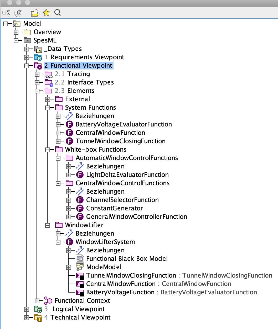
Below this node, there are the following specific subnodes:
- Elements -> System Functions: This package contains all system function elements. The functional white-box model of each system function is located below the system function element.
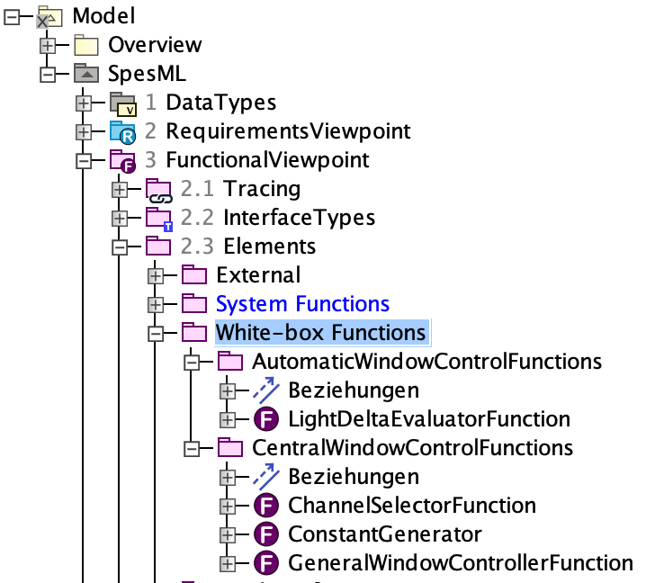
- Elements -> White-box Functions: This package contains all white-box function elements.
- System: This package contains the functional black-box model and the mode model of the system.
- Functional Context: This package contains the top-level view of the functional viewpoint and contains a diagram of the system under development in the context of its surrounding context functions.
Tracing information is gathered in the Functional Tracing Package, consisting of traceability matrices and impact maps.
How to Model
How to create System Functions
To specify a system function with inputs and outputs, follow these steps:
-
Navigate to the
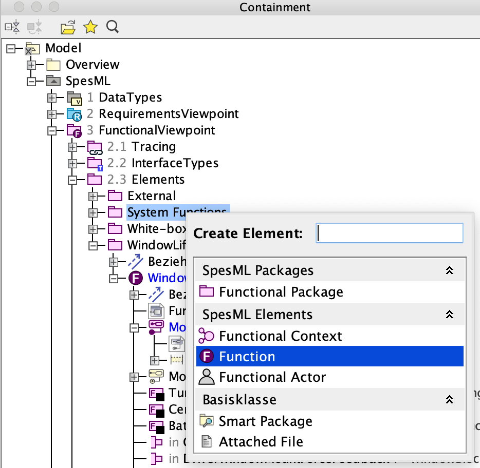
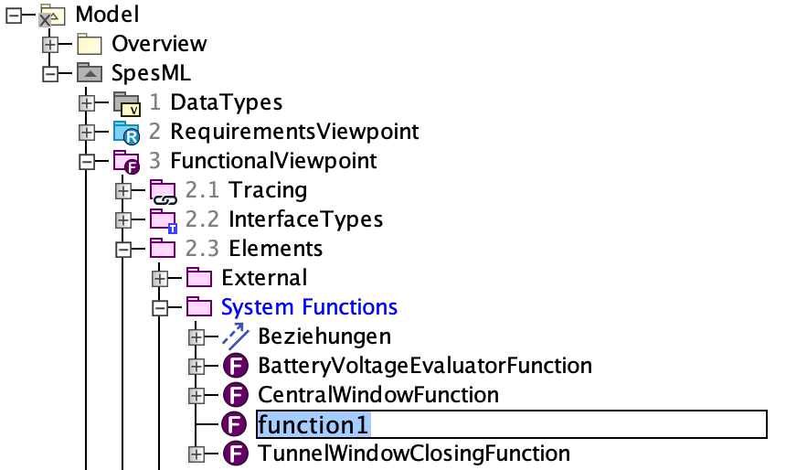
System Functionsfolder underFunctionalView -> Elements(or create it if it does not exist) -
Right-click on the folder and select Create Element. A dialog will open in which you can select elements you want to create. Select Function:
-
You are asked to choose a name for the system function:
-
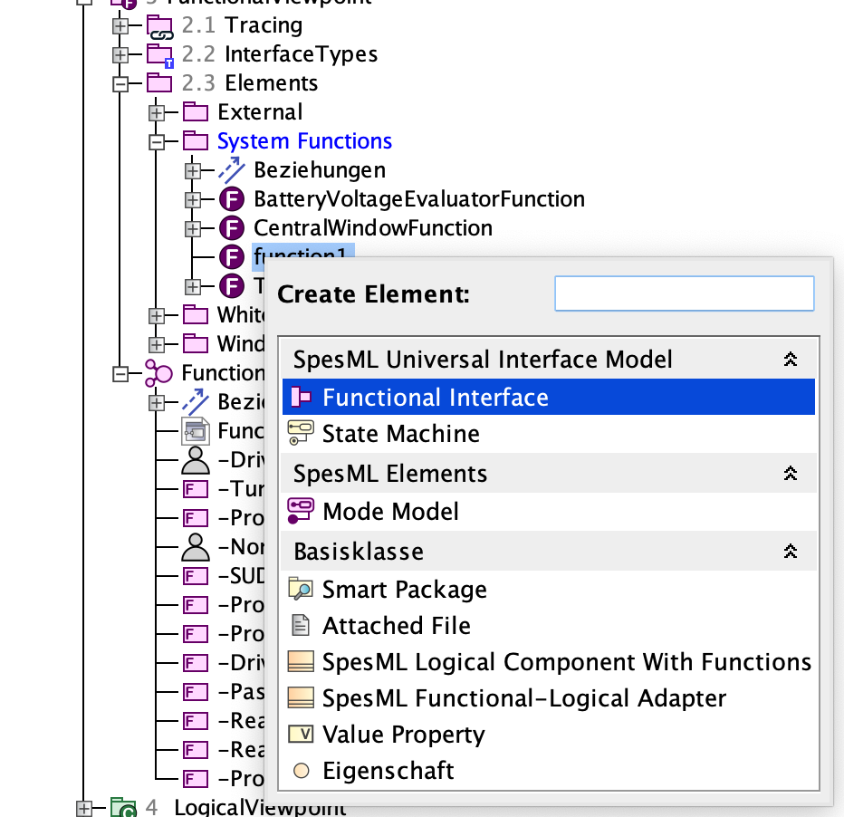
To add inputs and outputs to the system function, right-click on the system function, select Create Element, and select Functional Interface
-
Give the created port a name.
-
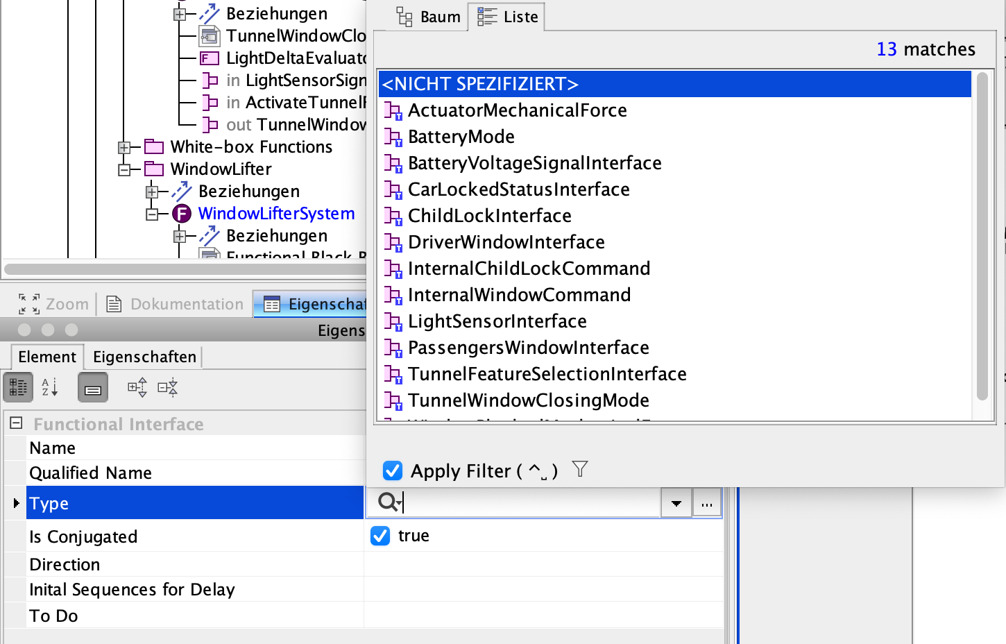
Assign a type to the port by selecting a defined type in the Type property field (see here how to create types).
-
Decide whether the port is an input or output port of the system function. Set the Is Conjugated property to
trueif the port is an input and tofalseif it is an output.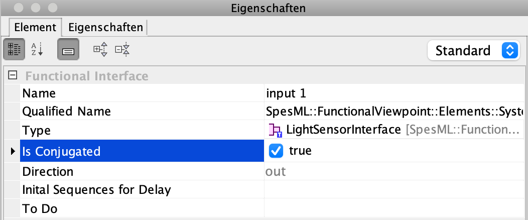
How to add a System Functions to a Functional Black-box Model
To create a functional black box model of a system, you can start by following these steps:
-
Navigate to the function in the containment tree, for which you want to model the functional black-box model (usually, this is the system function marked as system under development).
-
Right-click on this function and select Create Diagram:
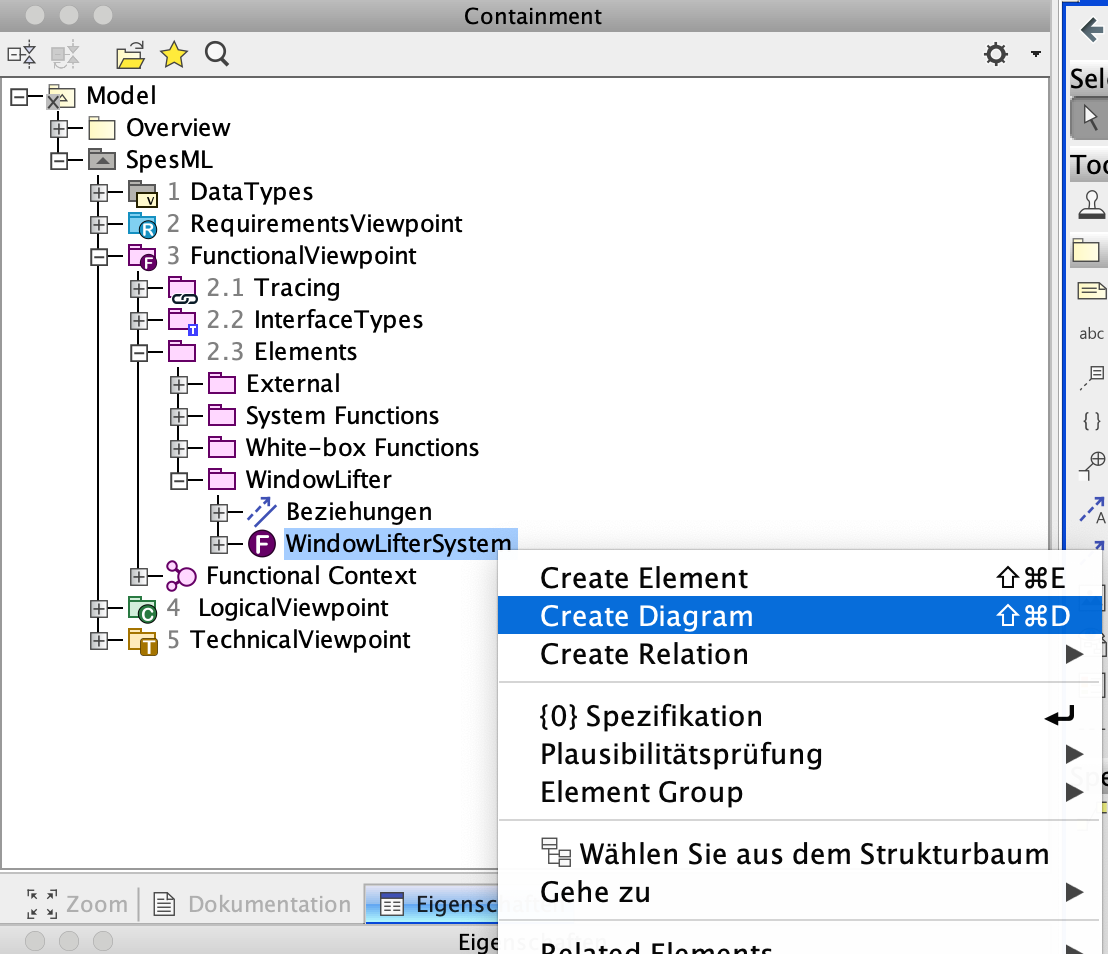
-
A dialog will open in which you can select the kind of diagram you want to create. Select SpesML Functional Internal Function Diagram:
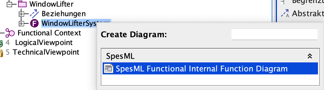
-
Another dialog will open that lets you select the elements of the function that you immediately want to display in the new diagram. For our function, we can select which of the interfaces we want to see in the diagram. Keep all of them selected and click OK:
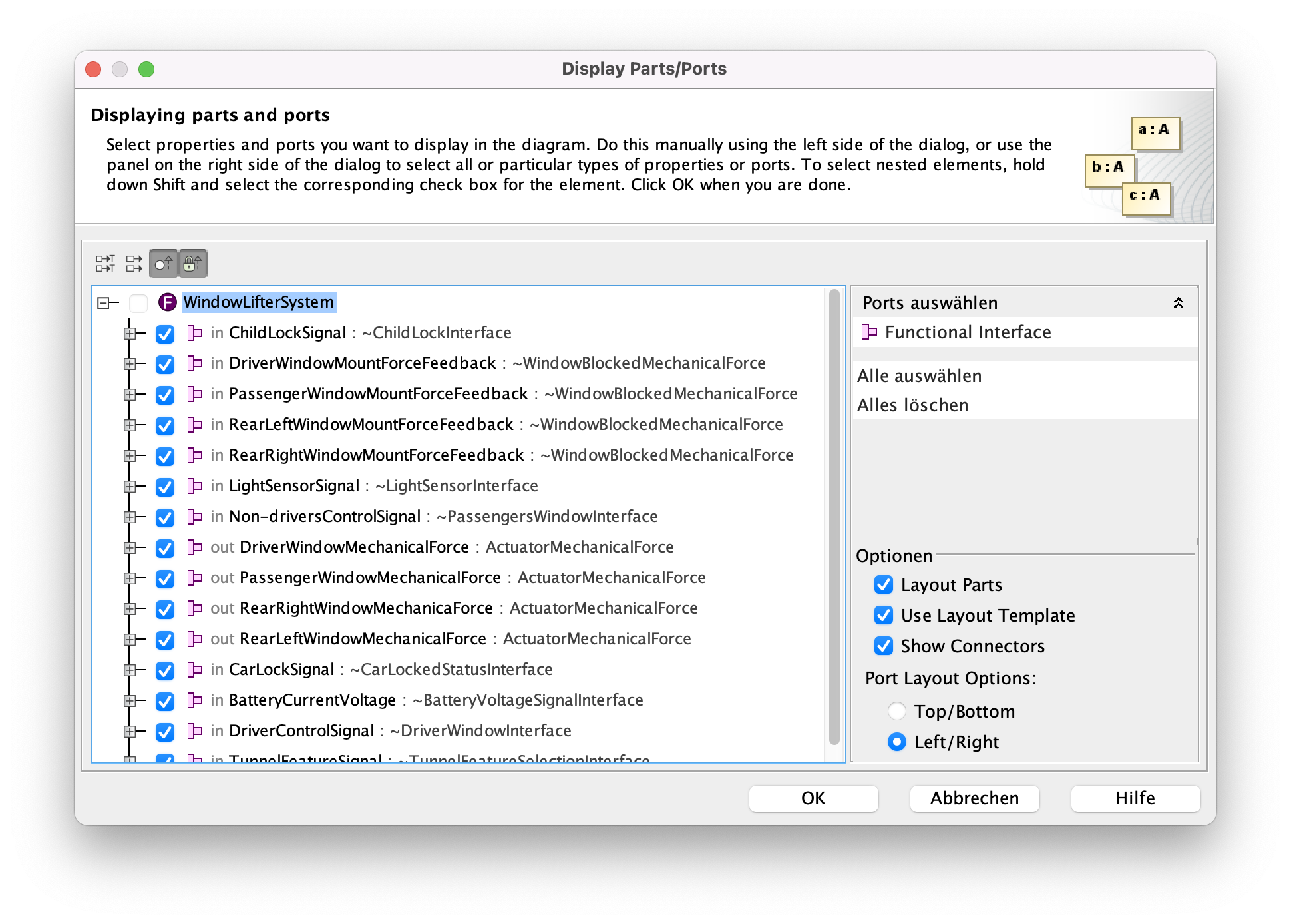
-
The new diagram will open in the editor. It contains only the elements we selected in the previous dialog - in our case the ports of the function.
-
You can add system functions to the diagram by dragging the functions from the containment tree and dropping them into the diagram.
-
Specify the function as a system function by setting the Function type property to
System Function.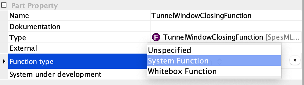
-
To display the interfaces of the new part, select the part and click on Display all Ports:
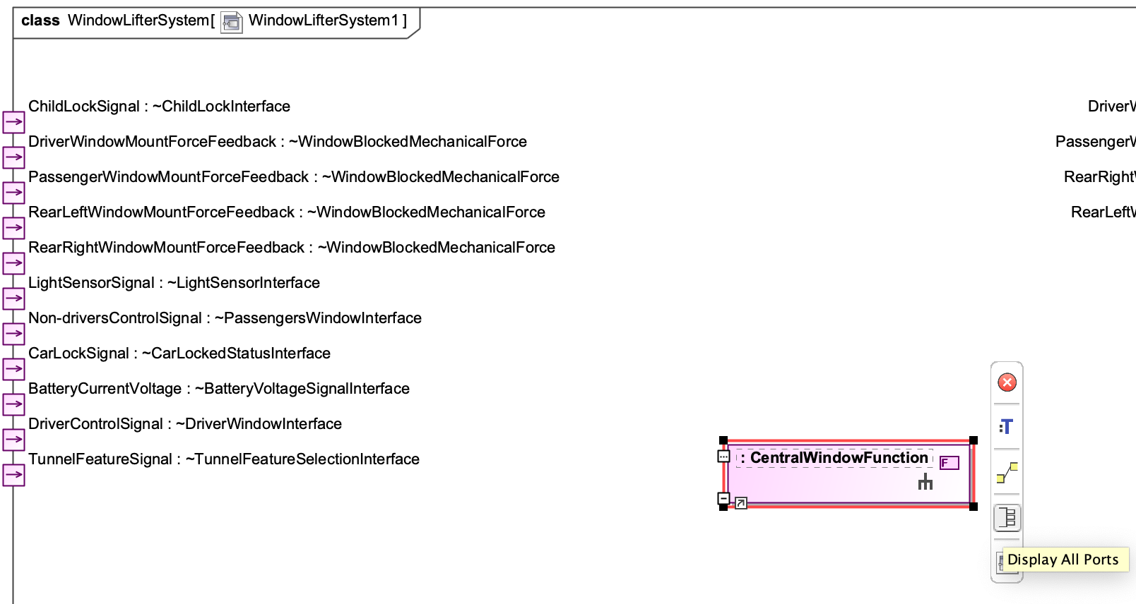
-
Connections between interfaces are created similarly: Select the port of an interface you want to connect to and click on Connector in the menu next to the port:
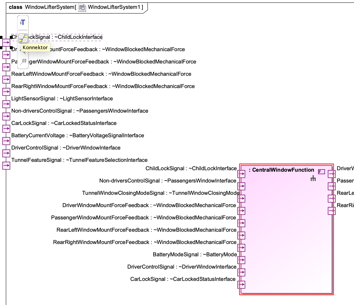
-
Your cursor will become the connector tool with which you can easily navigate to the target port for the connection:
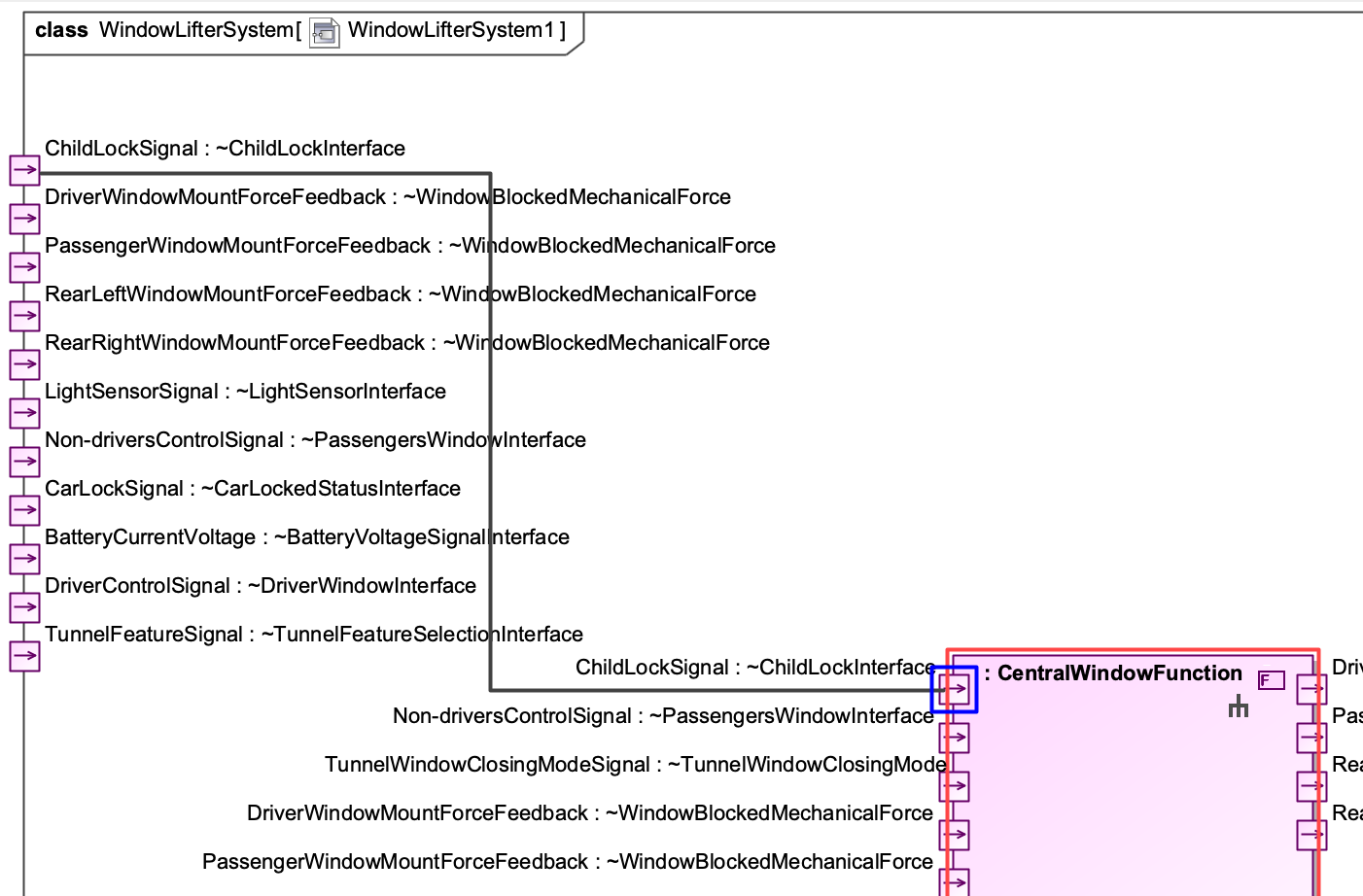
-
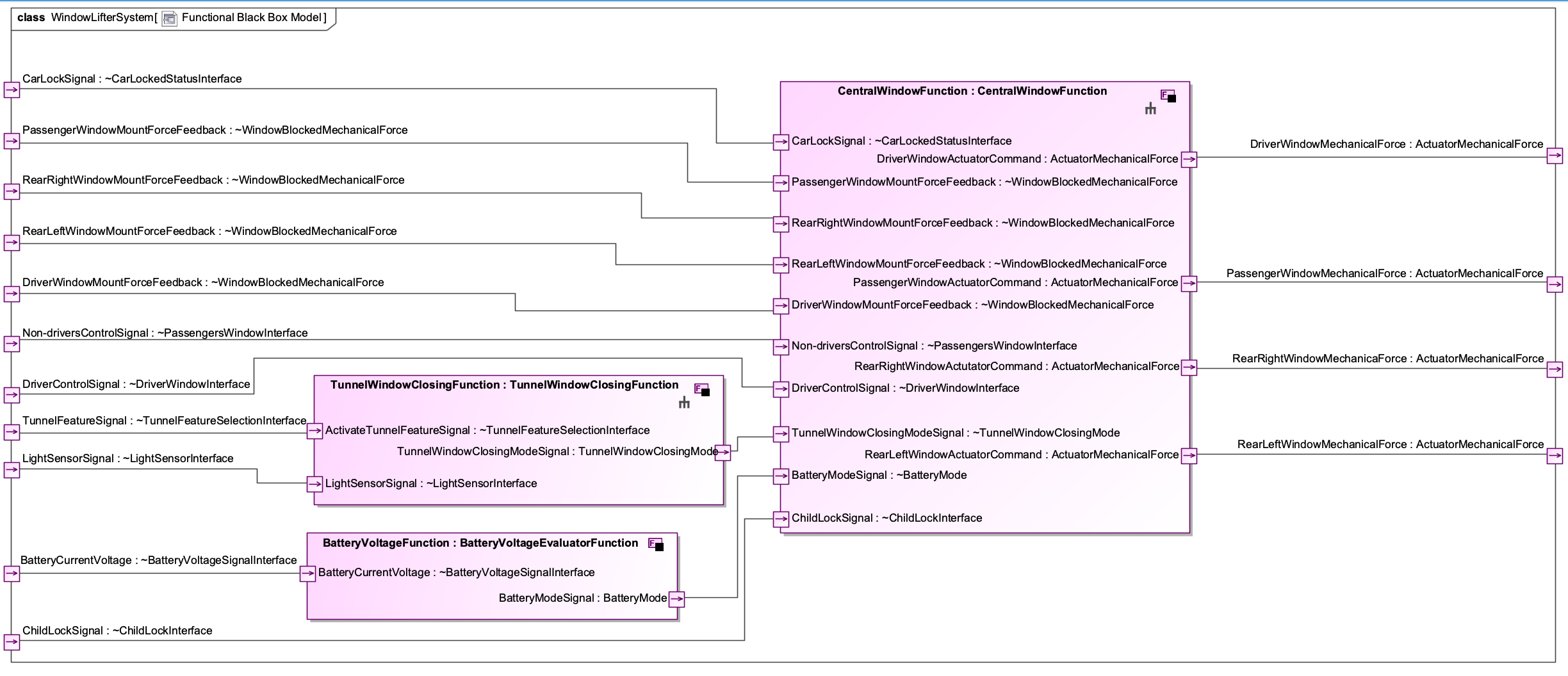
Using these mechanisms, you can create the functional architecture of the system:
How to create White-box Functions
To decompose a system function into a set of white box functions, follow these steps:
- Creating white-box functions works exactly the same as creating system functions. However, we recommend creating the white-box functions in a separate folder called White-Box Functions (or even in another sub-folder named after the system function for which the white-box function is created).
-
Navigate to the system function in the containment tree, for which you want to specify the functional white-box model.
-
Right-click on the system function and select Create Diagram:
-
A dialog will open in which you can select the kind of diagram you want to create. Select SpesML Functional Internal Function Diagram:
-
Another dialog will open that lets you select the elements of the function that you immediately want to display in the new diagram. For our function, we can select which of the interfaces we want to see in the diagram. Keep all of them selected and click OK:
-
The new diagram will open in the editor. It contains only the elements we selected in the previous dialog - in our case all ports of the function.
-
You can add white-box functions to the diagram by dragging the functions from the containment tree and dropping them into the diagram.
-
Specify the function as a white-box function by setting the Function type property to
Whitebox Function.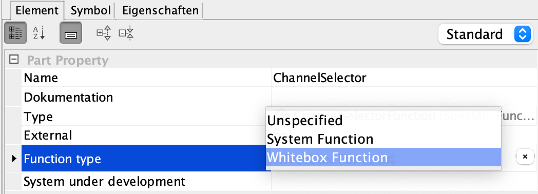
-
To display the interfaces of the new white-box function, select the function and click on Display all Ports:
-
Connections between interfaces are created similarly: Select the port of an interface you want to connect to and click on Connector in the menu next to the port:
-
Your cursor will become the connector tool with which you can easily navigate to the target port for the connection:
-
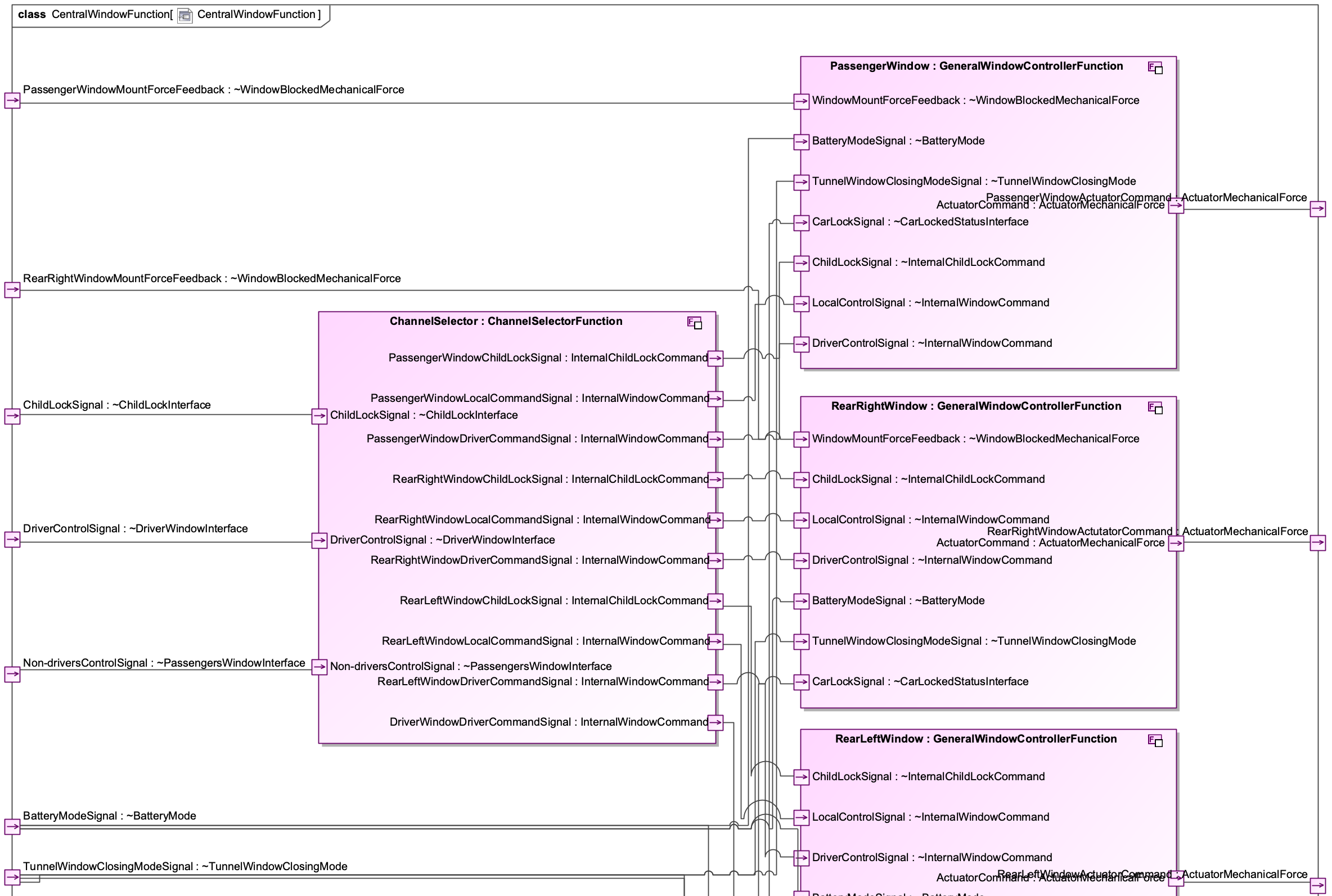
Using these mechanisms, you can create a functional white-box model for a system function:
How to create a Mode Model
To create a mode model of a system, you can start by following these steps:
-
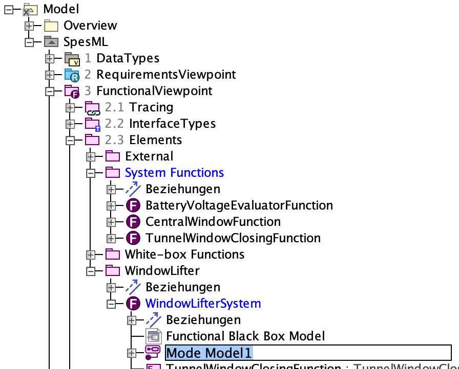
Navigate to the function in the containment tree, for which you want to model the mode model (usually, this is the system function marked as system under development).
-
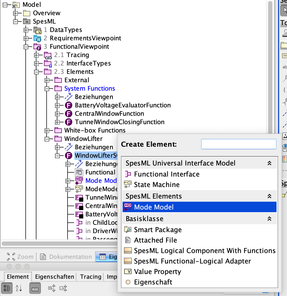
Right-click on this function and select Create Element. A dialog will open in which you can select the kind of element you want to create. Select Mode Model:
-
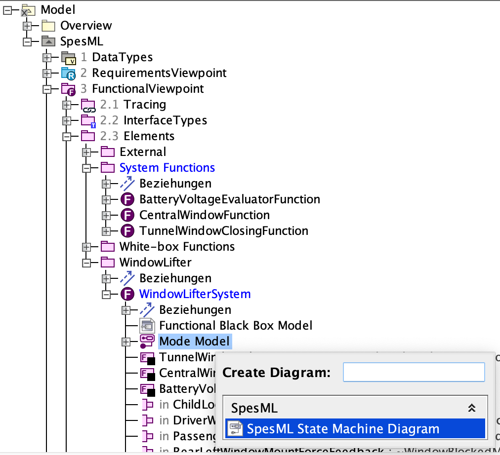
You are asked to choose a name for the element. You may simply call this element mode model:
-
Right-click on the mode model element and select Create Diagram to create a SpeML State Machine Diagram:
-
The state machine will open in the editor. Specify the mode model by creating a state machine.
Elements
Functional Viewpoint
This is the top-level structuring element of the Functional Viewpoint; it can contain other structuring elements (‘Interface Types’ Package, Functional Elements Package, or Functional Tracing Package).
There is exactly one Functional Viewpoint in a SpesML project.
 Functional Tracing Package
The Functional Tracing Package contains traceability matrices and impact maps. It especially contains a diagram for tracing functions to requirements
 Functional Interface Types Package
The Functional Interface Types Package contains all Functional Interface Types
 Functional Package
The Functional Package contains all elements of the Functional Viewpoint including System Functions, White-box Functions, Functional Actors.
 Functional Context
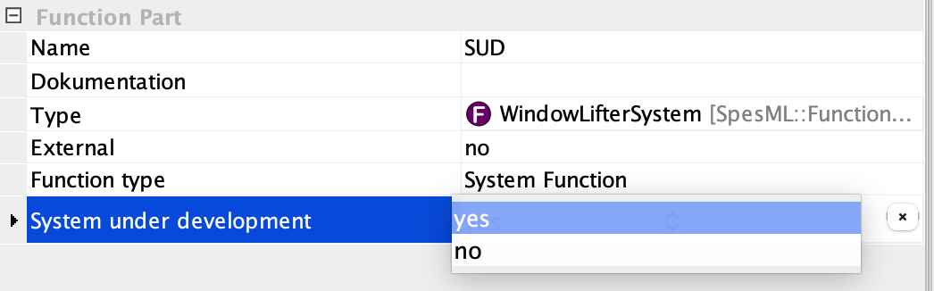
The Functional Context represents the top-level view of the system under development. It contains a single system function that represents the system under development and that must be marked as such by setting the property system under development to yes` (see below).
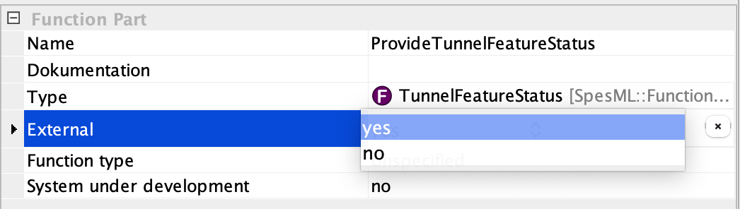
Additionally, the Functional Context contains a number of Functional Actors and external functions that represent elements of the context. A function can be defined as external by changing the property external from no to yes (see below).
The root function that represents the system under development contains a Functional Internal Function Diagram, which contains all system functions of the SuD.
 Functional Actor
Functional Actors represent human users in the Functional Context with which the system under development is interacting at runtime.
 Function
The Function is the central element of the functional viewpoint. After creating a Function element, the developer has to decide whether the function is a System Function or a White-box Function. This can be done by setting the property Function type (see below).
 Function Part
Functions (i.e., system functions and white-box functions) can be decomposed into a set of smaller interconnected functions. Any Function can become a Function Part by dragging it to a Functional Internal Function Diagram (see below). Note that system function decomposition is quite different from white-box function decomposition (as described in the Functional Viewpoint concept).
 Functional Interface Type
This element is based on a SysML Interface Block with a dedicated stereotype that allows defining where the element can be placed and other specifications. A Functional Interface Type is used to specify the type of a Functional Interface. It needs to be defined separately in a Functional Interface Types Package and can then be used to fill the Type property of a Functional Interface. A Functional Interface Type can either contain a Value Property (e.g., a specific enumeration) or a Channel (or multiple ones).
 Functional Interface
This element is based on a SysML Proxy Port with a dedicated stereotype that allows defining where the element can be placed and other specifications. A Functional Interface is used to connect different functional elements generically. It can be specified further by using Functional Interface Types and Channels to model the connection and information flow between the elements (via channels). A Functional Interface is nothing more than a port that can be attached to a function. If another function has also such a port/interface with the same Functional Interface Type], the user can connect these two ports with a Connector line.
 Channel
This element is based on a SysML Flow Property with a dedicated stereotype that allows for defining the flow direction and other specifications. Its concept is explained in the Universal Interface Model. It can be added as an element to a Functional Interface Type. Channels enable signal/information transport between elements that are connected with an interface connection that has such an interface type (with a channel). A channel has a type (the type of the transported signal/information), which can be any pre-defined basic data type or a new user-defined data type (see Data Types).
Diagrams
 SpesML Functional Impact Map
This relation map shows Functions and what elements from the Logical Viewpoint are tracing these elements. By default, all Functions are shown but it is also possible to drag & drop a single Function to the relation map to show only the particular relationships.
SpesML Functional Tracing Map
This relation map shows Functions and to what Requirements these elements trace. By default, all Functions are shown but it is also possible to drag & drop a single Function to the relation map to show only the particular relationships.
 SpesML FunctionToRequirement Matrix
This diagram can be used to create and visualize trace relations between functions and requirements. Possible trace relations are satisfy and requires
 SpesML Functional Internal Function Diagram
This diagram is based on a UML Composite Structure Diagram/SysML Internal Block Diagram and provides a reduced diagram toolbar related to SpesML. Note that intentionally Functional Parts cannot be created using the diagram toolbar. Instead, it is recommended to create these elements by dragging/dropping a Function to the diagram.
Modeling Rules (Well-formedness Rules)
Functional Context
- The functional context must include exactly one system function that represents the SuD.
System Functions
- System functions must have at least one output port connected to an output port of the overall SuD or at least one input port connected to an input port of the overall SuD.
- Recommendation: A system function models behavior, so the name should begin with a verb (e.g., controlWindows)
System Function Hierarchies
- There exists exactly one root system function, the SuD
White-Box Functions
- Each functional white-box model must be related to exactly one system function.
- Each system function must be related to at most one functional white-box model.
- The interface of a system function (i.e., inputs and outputs) must be reflected in its related functional white-box model, i.e., each input and output port of the system function must also be a free input or output port in the functional white-box model (i.e., a port without any flow property).
- Each white-box function must be related to at most one logical component that implements this white-box function.
Mode Model
- There is at most one mode model per system.
- Each value that can be sent over a mode channel (i.e., a channel between system functions in the functional black-box model) must have a corresponding state in the mode model.
- Transitions in the mode model do not have any guards or actions as they simply define potential sequences of modes.
- A mode model has an initial state but no final state.