Tracing between Views and Layers of Granularity
This chapter provides a description of the SpesML Tracing Concept i.e. how elements from the SpesML Views can be properly traced and related to each other. Establishing tracing relationships is often a tedious task for the user, so we recommend making this process as easy as possible. In general, it is advised that only those tracing relationships are established that are absolutely necessary - i.e. the amount of tracing relationships the user has to manually define should be kept at a minimum, and second, each trace should have a precise semantic meaning. In SpesML we introduce a set of stereotypes to allow easy setup of tracing matrixes (see below) and other customizations. A detailed description of the implementation of the tracing concept can be found here (see Tracing Plugin).
Models in SPES
In the SPES approach, the architecture description of the system under development (SuD) is structured with the help of predefined viewpoints (see Tracing Plugin). Each viewpoint defines a set of models and model elements, for modeling the respective view of the SuD.
The model elements are related to each other both within a single view and across view boundaries. Relationships between model elements of a SuD from different views are n:m in general. This means, that a model element in one view is “implemented1” by m model elements in the other view, and vice versa a model element of this other view may “implement” parts of n different model elements of the first view. Such a situation strongly limits the options for semantically expressive relations and analyses. Therefore, in our approach we recommend a practical compromise (design recommendations) between generality and the possibility of enabling semantically expressive tracing relationships between model elements. There may be usage scenarios where a different approach has to be taken. This then comes at the expense of the semantics of the trace relationships.
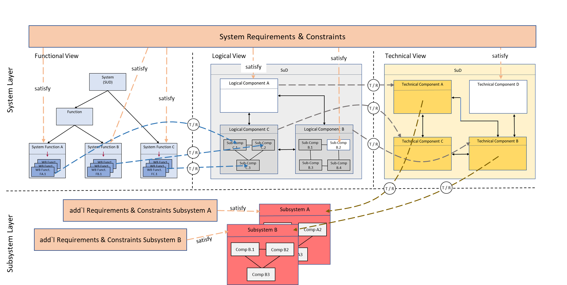
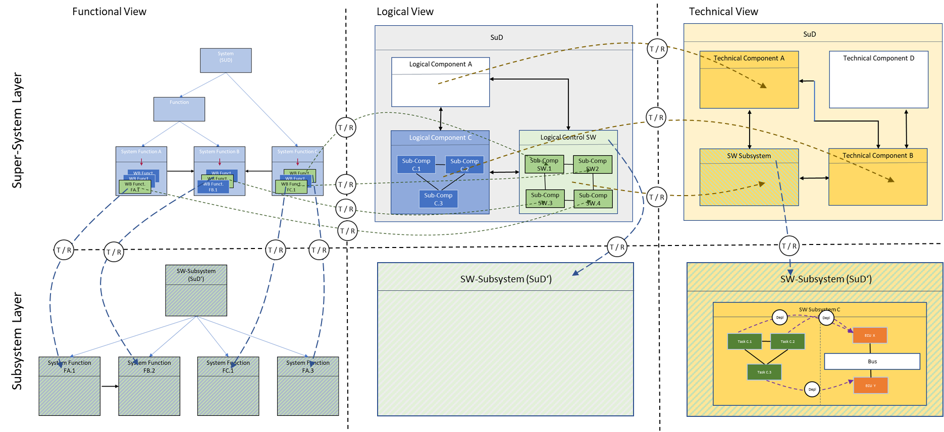
Figure 2 gives an overview of the trace relations of an SuD across the different views and across layers of granularity, which are described below in more detail. In SpesML we use the satisfy relation for tracing between requirements and the model elements from the different views and the realizes relation (realizes (redundant) respectively) for tracing between the views (different architectures).
Note: Unlike indicated in Figure 2, the satisfy and realizes relationships always points backwards from the implementing model element to the implemented model element.
Requirements
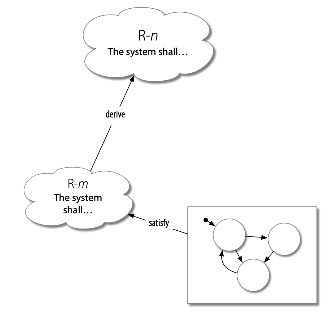
In SpesML, requirements are described as natural language statements. They may be allocated to architectural elements (modeled through a satisfy relation from the architectural element to the requirement), or refined into more detailed requirements (modeled through a derived relation from the more detailed requirement). The combination of satisfy and derive allows the representation of justification chains linking architectural elements to high-level stakeholder needs or to obligations arising from the development context, such as compliance.
Other tracing relations can be used in the context of modular subsystem development or to link simulation setups as verification evidence or explanatory information to requirements.
As the main focus of SpesML is on the architectural models of the functional, logical and technical viewpoints, SpesML prescribes no specific requirements engineering method. Nevertheless, it is good practice to follow certain guidelines; for example, the requirements guidelines of INCOSE are a suitable starting point.
Requirements are not isolated model elements, but are typically related to other requirements and other model elements through tracing relationships. A listing of all tracing relationships, supported in SpesML can be found here ( Requirements Viewpoint)
Note: In order to follow our advice to keep the number of trace links small, it is a good idea to already differentiate at the requirements level what is necessary for the different views.
Tracing Relationships between Elements in the Functional and Logical Views
It is important to understand how model elements of the functional view (i.e. system black- box and white-box functions) relate to model elements of the logical view (logical architecture and logical components). In general, it is possible to design a logical architecture that does not take into account design decisions from the functional architecture view which may lead to an n:m relation, i.e., a white-box function is realized in the logical architecture by n logical components and a logical component realizes portions of m white-box functions, thus strongly limiting the semantics of the tracing relations.
Therefore, for the SPES methodology we suggest a design pattern that provides a closer connection between the system function models in the functional view and the structure of the logical architecture by using the concept of system function white-box models (see</a> Functional Viewpoint), to achieve a meaningful tracing2 relationship between the model elements of the views.
Please note that following our design recommendations given in this document will always result in an architectural design decision.
We suggest to design the white-box models (chains of effects) of the system functions in the functional view with the structure of the logical architecture in mind to build a bridge between the functional and the logical architectures. In a design decision, a structural architecture is developed from the set of white-box functions by uniquely mapping, i.e., tracing white-box functions to logical components (see Figure 3). To that end the logical components are decomposed into sub-components that implement exactly one white-box function. Sub-components can be combined into logical architecture components by applying the Universal Interface Model (UIM). The sub-components then represent a refinement of the white-box functions (arrow labeled T/R in Figure 3). In the tool this is modeled by a realize relation from the logical sub-component to the white-box function. Composition of all these sub-components yields the syntactic and semantic interface of the respective component (again by application of the UIM). The interfaces of such sub-components (syntactically and semantically) are derived from the interfaces of the white-box functions via a refinement relation. This results in a network of communicating logical sub-components to which each white-box function of the functional view of the SuD is uniquely assigned.
In our tool implementation, system functions and white-box functions are SpesML function elements, which are derived from the SysML Block element with SpesML Function stereotype applied (see for more details). As a consequence, traces are provided on the basis of model object types (the SysML Block elements). Thus, the realizes relation links the types of the logical sub-component and the white-box function.
In most cases, this distinction is not of practical importance, since in most cases for each white-box function we have a 1:1 relationship between type and instance. However, there are two exceptions we need to discuss:
-
It is possible for a white-box function to be mapped to more than one sub-component. For example, to model redundancy in the logical architecture, it is necessary for a white-box function to be implemented as a sub-component in more than one logical component. Our approach supports such a scenario as long as the whole type of the white-box function is implemented through the corresponding sub-components. To indicate this case, we use a realizes (redundant) relation to the white-box function.
-
Our functional model of a system can be viewed as a network of communicating instances of white-box function types, where in most cases the network would contain only one instance of each type. There may be some white-box functions where we have more than one instance of that white-box function, i.e., there may be white-box functions that occur in multiple white-box models. Mapping to logical components in such a situation needs a design decision. Two options are available:
-
Each instance of the white-box function is implemented by a separate sub-component in the logical view. This case will be modeled by the realizes (redundant) tracing relation.
-
We may choose to implement the multiple instances of the white-box function through a shared sub-component in the logical view. As we are tracing to the white-box function types only, we can model this case with the standard realizes relation.
-
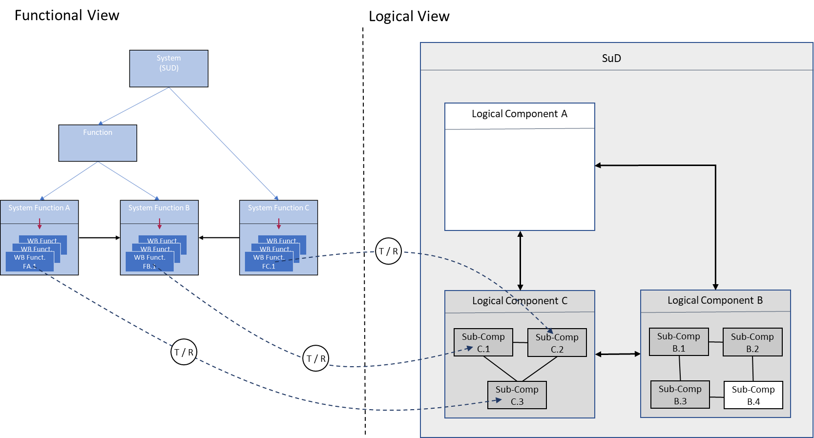
Note: The logical architecture (logical components) can also contain further (sub-) components that are defined by additional requirements (i.e. requirements that are not covered by functions in the FVP). Those (sub-)components will not have a direct tracing relation to a white-box function. An example of these are requirements that arise through design decisions (white boxes in Figure 3).
Definition of Software-Components in the Logical Architecture
In the SpesML approach we consider predominantly cyber-physical systems, i.e., systems that combine cyber capabilities (computation and/or communication activities) with physical capabilities (motions or other physical processes). The cyber parts of the system hereby control the physical parts3 (physical components).
Therefore, we are often interested to model the behavior of the SuD as observable at the interface between the software- and the physical part (see for more details). In order to achieve this, we want to design the control parts as independent components, called Software Subsystems, already in the logical architecture structure model.
Depending on the project at hand we have three options:
-
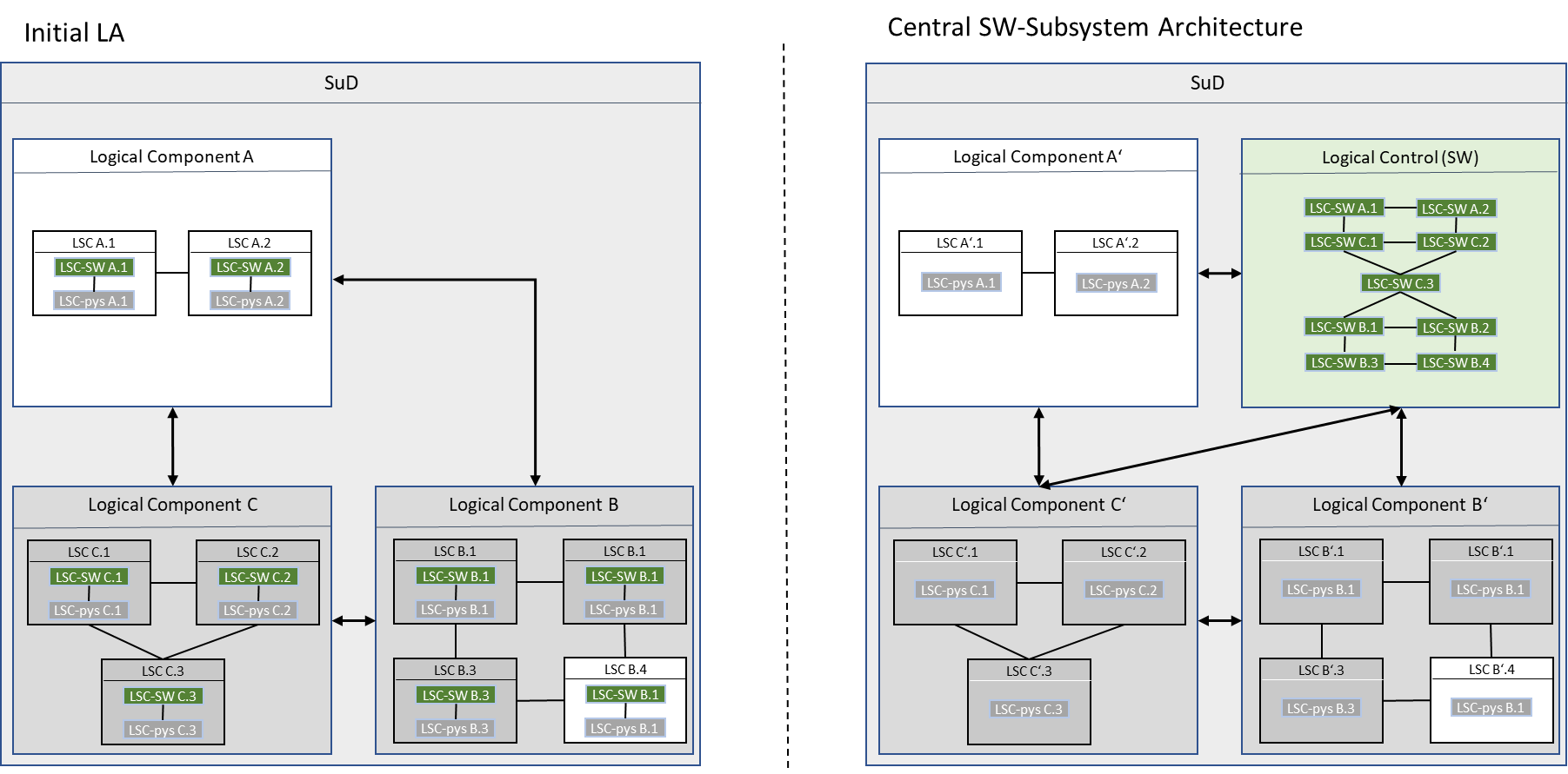
The split into cyber functions and physical functions can already be done when designing the functional white-box models, i.e., we identify the white-box functions which correspond to the cyber part of the SuD. In this case, we already have a structure of sub-components in the logical architecture consisting of software components and physical components with appropriate interfaces between these sub-components, which can be rearranged to form logical components that implement the cyber and the physical parts of the SuD (Central SW-Subsystem Architecture4). This approach has the advantage that we can define a continuous semantical tracing between all the modeling views of the SuD. The drawback is, that we make an implementation decision already in the functional models which may not be appropriate in all cases.
-
If the white-box functions are not already designed according to this split, we suggest to further decompose the sub-components in the logical architecture (Figure 3) into a cyber and a physical part. These sub-sub-components can now be rearranged and composed to achieve the targeted split (see Figure 4). This approach does not require implementation decisions already in the functional view, but has the disadvantage that the behavior models of the white-box functions can no longer be used directly to model the behavior of these sub-sub-components, and in addition, there is a disruption in the tracing between the modes of the functional view and the models of the Central SW-Subsystem Architecture since white-box functions are now split over several logical components.
-
Options 1. and 2. can also be combined: The central SW-subsystem architecture. Hence, the initial logical architecture can be seen as an intermediate step in the development process only, whose models are no longer needed in the further course of the development. We recommend to reproduce this refinement step in the white-box models of the functional view and decompose the corresponding white-box functions also into a cyber and a physical part. The sub-components of the central SW-subsystem architecture then realize the refined white-box functions.
It should be noted, that
-
in all cases the (sub-)sub-components are modelled according to the Universal Interface Model which enables composition and therefore also is also used to model the behavior of the SuD and its architecture components, in particular the behavior at the interface between the cyber and the physical parts and
-
if the initial logical architecture should be kept for further development the trace relation between the elements of the initial logical architecture and the SW-Subsystem architecture can be used.
Tracing Relationships between Elements in the Logical View and Technical View
As with the transition from the functional to the logical view, the relationship between logical and technical architectural components is n:m in general, if the technical architecture is designed without the logical architecture in mind.
Again, the goal is to create meaningful tracing relationships between the model elements of the views. Therefore we suggest to develop an initial architecture in the technical view that has the same component structure as the logical architecture, which yields a 1:1 tracing relation between logical and technical components on this layer of abstraction (see Figure 5). The tracing is modelled through a realizes relation from the technical components to the logical components. The components of this initial technical architecture can be decomposed in further development steps.
Note:
-
As with the logical architecture, the technical architecture can also contain further components that are defined by additional implementation requirements which will not have a direct tracing relation to a logical component.
-
It is also possible that logical components are implemented multiple times by technical components in the technical architecture, e.g. to model redundancy in the technical view for the first time. We use the trace realize (redundant) to model this.
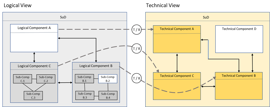
The syntactical interface of these technical components is then a refinement of the related logical components. Even if we propose a 1:1 relationship between logical and technical components, the interface refinement has a large impact of the details of the technical architecture.
Tracing Relations for the Software Execution Subsystem
The runtime part of the software execution subsystem (the Central SW-Subsystems in case of a CPS) is described by a set of (executable) tasks that process inputs to outputs, or by a bus message catalog that contains all messages representing the technical data flow between these tasks (see task architecture).

In general, the software tasks can be designed independent from the sub-component structure of the logical control component. However, in practice we will often use these sub-components to derive a set of software tasks necessary to implement the software execution subsystem, defining a 1:n relationship between the sub-components and the software tasks. This in turn defines a refinement relationship between the logical sub-components of the logical control component and the tasks of the software execution subsystem (see Figure 6). The tracing is modelled through a realizes relation from the software tasks to the logical sub-components.
Deployment Models
Deployment models allocate the software tasks to hardware architecture elements to provide an integrated platform-specific solution model for the software execution subsystem. Such a mapping is necessary to define the appropriate execution (and communication) resources for given software architecture artifacts.
When modeling design-time software artifacts (e.g., specific middleware properties), further mappings are required in the sense that run-time software artifacts are mapped to design-time software artifacts (e.g., partitions) associated with a specific hardware execution resource.
A detailed description of the allocation models used for deployment can be found here: link
By defining “allocate to” traces in allocation metrices (see, e.g., link) between software tasks and execution components, it can be specified/modeled which software task should be deployed on which execution component. The cardinality of these allocation traces must be n:1 for all software tasks to execution components, i.e., a software tasks can only be deployed on exactly one execution component while an execution component can have multiple software tasks that are deployed on it.
Tracing of Context Elements
To model the interaction of the SuD with its environment (e.g. for simulation purposes) we have introduced context models for each view in SpesML. Obviously, these context models are not independent of each other. Therefore, it is interesting to understand the relations between the elements of these context models.
Context Relations Between Functional and Logical View
In the functional view, the context is modeled from a purely functional perspective. Functions in the context (we call them context functions) can be performed, for example, by human actuators or by external systems. While in the logical view the focus is on structural elements i.e. external systems, called context systems (these can also be human actuators) by which the functions are performed.
The tracing relations between context functions and context systems are analog to the relations between system functions and logical components: Context systems realize context functions. Context systems that provide redundant functions are modeled with a realize (redundant) relation.
Note: We strongly recommend modeling the structural context in the logical view in such a way that there is an n:1 relation between context functions and context systems (i.e., a context system realizes n context functions, while each context function is realized as a whole by exactly one context system or by multiple context systems in the redundant case).
Context Relations Between Logical and Technical View
At the highest level of abstraction, there is a 1:1 relationship between logical context systems (in the logical view) and technical context systems (in the technical view). Tracing relations between these context systems are again realizes and realizes (redundant) respectively.
Tracing between Layers of Granularity (Tracing between Subsystems)
The structuring of the models in the individual views described in the previous sections allows components from the technical view to be viewed as independent systems (we call them subsystems5) that can be further developed independently. Each subsystem is treated as an independent system under development. It is important to note that subsystems always have an independent architecture and an associated technical implementation.
Hereby, it is irrelevant which methodology (processes, methods, tools) is used to develop the subsystems. In the SPES methodology all such subsystems of a super-system are clustered in one layer of granularity. Typically, only a careful selection of the technical components will be processed as subsystems.
As subsystems are derived from components of the technical architecture, there always exists a (trivial) model relation between the subsystem and the respective technical component (due to the construction of the layer of granularity).
Of course, the SPES methodology can also be applied recursively to subsystems (see Subsystems). In the following we will assume that subsystems are also modeled according to the SPES methodology and discuss which additional model relations can be identified.
Tracing Relations Between Systems on Different Layers of Granularity
How models of the architecture of the subsystem and the technical implementation can be derived from the models of the super-systems depends on the nature of the tracing relationships of the models in the super-system.
As mentioned above, the model relationships between the models of the functional view and the logical view or the logical view and the technical view of an SuD are n:m, respectively, in the general case. In such cases, meaningful model tracing relations between the super-system and the subsystem for the models of the functional or the logical view and model integration of the models of the subsystem into those of the super-system cannot be identified.
Note: Whether an integration of the subsystem models into the models of the super-system is required at all, depends on the situation of the concrete development project.
Development Against Assumed Requirements
Subsystem developers face the problem that the requirements for the subsystem are not yet finally defined. In such situations - particularly in the highly work-sharing automobile industry - subsystems are developed first against assumed requirements, which are brought into the super-system context at a later time.
The following requirements must be met by the subsystem:
-
A subset or refinement of the textual requirements of the super-system.
-
Super-system constraints with reference to the subsystem.
-
Additional constraints on the subsystem arising, for example, from context relationships.
-
Requirements that result from the interface models of the super-system in the FVP, LVP, and TVP.
-
Subsystems may still have additional requirements as well as their own context that must be considered for their development.
In the case of integration on model level, requirements across layers of granularity are related with match links. SpesML offers two additional tracing relationships to express this situation (see Figure 7 for an example):
-
Require (from model element to requirement): This relationship states that a model element - typically a function of the FVP or a component of the LVP, or the TVP - has certain expectations that are to be fulfilled by the context of the model element.
-
Matches (from requirement to requirement): This relationship expresses that expectations are provided by properties guaranteed by the subsystem.

A verification obligation also for these two relations arises from their use in a model.
Tracing of Architecture Models Across Layers of Granularity
We always use the paradigm of the universal interface model to integrate a subsystem into the super-system. In particular, the integration of the subsystem is always done as a black- box based on its syntactic (and semantic) interface.
Following the design recommendations from this document for each subsystem, as well as for the super-system, we have traces to a unique component in the technical view of the super-system that represents the subsystem and can be traced back to the corresponding models in the logical architecture of the super-system. The universal interface concept allows the subsystem model to be integrated into both the logical view models (syntactic and semantic) and the technical view models (syntactic), each as a black-box.
Tracing of the Operational Context Across Layers of Granularity
The logical view contains also models of the operational context. Hereby the operational context of the subsystem is a projection of the context of the super-system defined as follows:
-
The operational context is always defined with reference to the system being developed. From the definition of a subsystem and given the proposed 1:1 relation between technical and logical components, a subsystem is represented by a component in the logical architecture of the super-system.
-
The operational context of the subsystem contains all context elements from the super-system that have a direct channel to the component the subsystem in the logical architecture of the super-system.
-
Furthermore, the operational context of the subsystem contains all components from the logical architecture of the super-system that have a channel to in the component representing the subsystem. It should be noted that these context elements are not 1:1 copies of the components of the logical architecture of the super-system, as their behavior might be additionally influenced by the context of the super-system. Only the syntactic interfaces of those components are identical.
Tracing for Software Execution Subsystems
We now discuss some additional tracing relations we can derive for a software execution subsystem that is developed using our SPES approach.
Following the design recommendations described above (i.e. identifying the sub-functions that will be implemented in SW already in the white-box models and building a 1:1 relation between the logical and technical components) and assuming that the model of the software execution subsystem follow the SPES approach, further semantically rich tracing relations across the layers of granularity can be defined.
If white-box functions that are realized in SW have already been identified in the white-box models of the functional view of the super-system those white-box functions become system function of the software execution subsystem (at the next layer of granularity), which means that meaningful tracing relationships (black-box tracing) between system functions of the software execution subsystem and those white-box functions exist:
-
The software execution subsystem defined in the technical architecture of the super-system becomes the new SuD in the next layer of granularity, and
-
we can identify a logical component in the logical architecture of the super-system that represents the subsystem, and
-
white-box functions in the functional view of the super-system may become system functions on subsystem level.
-
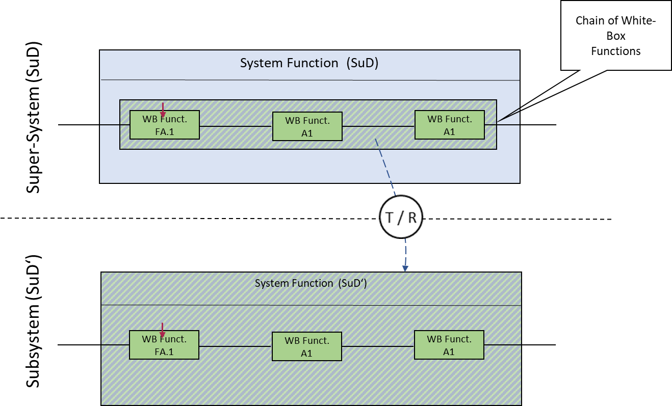
However, if a white-box-function becomes a system function on subsystem level depends on how fine granular the white-box functions have been defined at the super-system level: In case, there exist white-box functions that do not have an interface at the associated system function’s boundary (i.e., there are chains of white-box functions within a system function that can be combined to form a larger white-box function without affecting the structure of the logical components) then the whole chain is traced as a system function on subsystem level (Figure 8; of course there will be additional tracing relations between the models of the subsystem not shown in the figure).
—————-
-
From a formal point of view this “implementation” can be modeled as a refinement relation between the models under consideration. ↩
-
Trace in this context means, that we link a logical component to the functions modeled in the white-box function, expressing their relation. ↩
-
Here, physical parts stand for all parts of the SuD that are not part of the control SW. Therefore, physical parts can also contain SW shares. ↩
-
It should be noted that is also possible to define architectures that comprise multiple SW-subsystems or architectures where physical components still include parts that are implemented in software. ↩
-
A prominent example of a subsystem is the SW subsystem we discussed above. ↩