Technical Viewpoint
Content:
General Concept
TODO: any references / citations needed? Maybe AF3/DSE in the allocation section?
The technical viewpoint and its instances, the technical views, are mostly concerned with the question of how to get from the platform independent models of logical viewpoint (logical components) to platform specific models (technical components). In the following, we describe all models of the technical viewpoint including the software execution subsystem.
In general, we see generic technical models on the first granularity layer (the overall system), which can then be refined to more specialized models on the next granularity layer(s). An example for such a refinement/specialization is the software execution subsystem. This is why we divide this chapter of the technical viewpoint into two parts. First, we present the more generic models of the technical viewpoint on the system layer and afterwards, the models of the software execution subsystem on a lower layer of granularity.
The presented approach targets various scenarios that may emerge in systems engineering, e.g.:
- Integration of technical components from various engineering disciplines, e.g., integration of a mechatronic component (incl. mechanics, electronics, and software). Such a scenario can be supported by specific technical components and their dedicated interfaces to other technical components.
- Engineering a new system architecture in terms of hardware topology, e.g., with a more centralized software part (see software execution subsystem). This requires an overview of computation resources and communication resources that are intended for the new system.
We also envision combinations of these. The proposed approach enables that.
In SpesML, we do not provide behavior models for technical views since we are not in a position to fully describe the behavior of all possible technical components in detail. It is possible to use dedicated external techniques if such a detailed description is needed. However, we provide the input for such behavior modeling and further development steps like deployment and scheduling analysis through our technical viewpoint concepts like tracing logical components to technical components and software elements, the software element architecture in general, the platform architecture, their interfaces, and the deployment of software elements to execution elements. In contrast to other viewpoints, the technical viewpoint only considers the syntactical interface of the universal interface model (UIM).
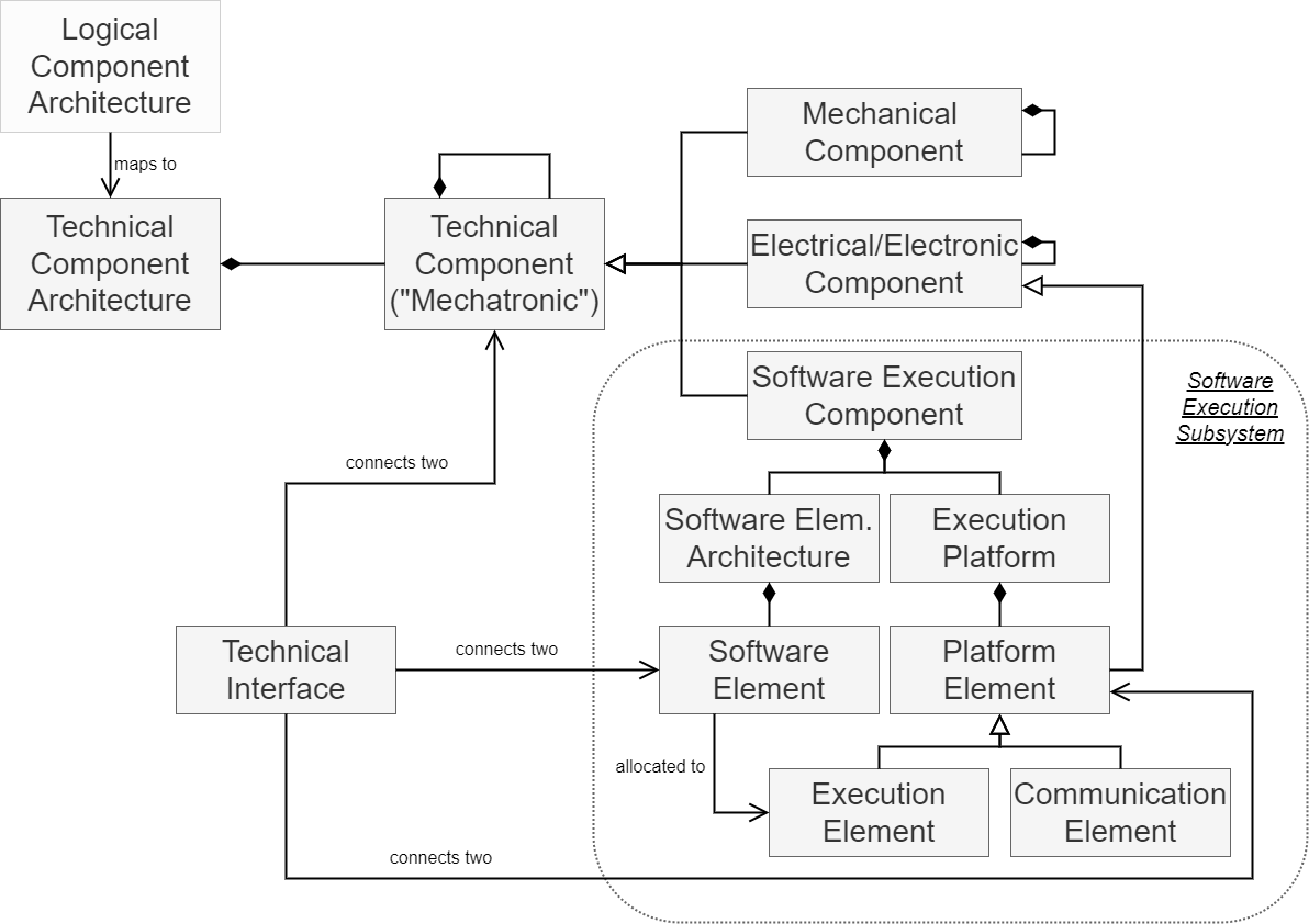
The following sections will cover first the more general technical components, mainly on the first layer of granularity, and afterwards the software execution subsystem in detail. Figure 1 gives an overview to understand the relations and possibilities of the technical viewpoint.
Models on the System Layer
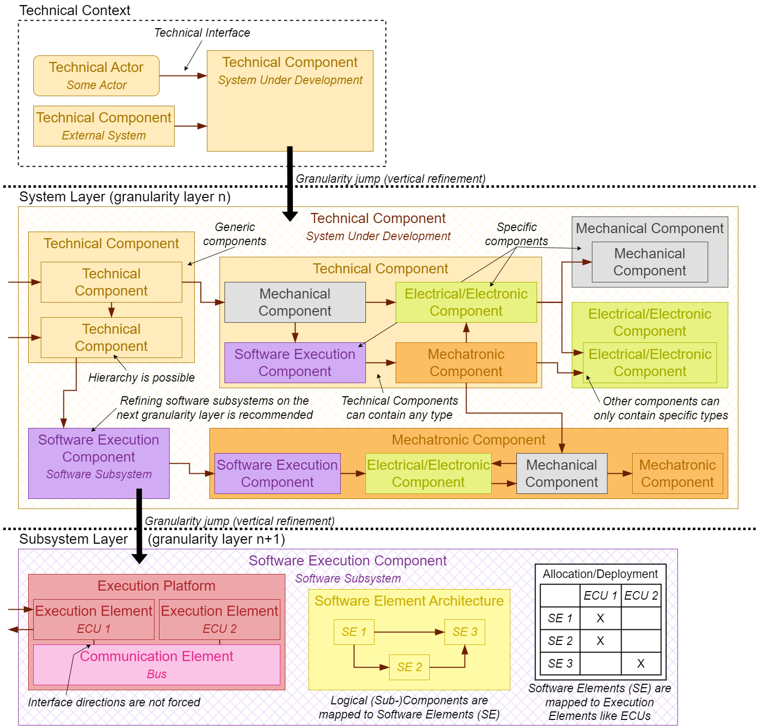
The first model of the technical viewpoint is the technical component architecture. It models the existing technical components of a system and how they are connected. This architecture is most important on the system layer of granularity, but it can also be used on all lower layers to describe the technical architecture of each subsystem. In this section, we will first present all the elements of such a technical architecture and how it is structured. Afterwards, we will point out the connection of the technical architecture to other views and the resulting tracing relations. As a final note, we will briefly talk about how redundancy can occur in the technical architecture. In addition, we provide in Figure 2 an abstract example of how a technical architecture can look like across granularity layers.
Elements and Structure
Components. On the system granularity layer, the technical architecture of the system is described using components. These components represent the system either in a generic way or more specific using models of the respective technical engineering disciplines. The generic component is called technical component and can be used for everything in any discipline. If the content of a component can be assigned completely to one specific discipline, a more specific component type can be chosen to represent this. Referring to this, available disciplines are mechanical engineering with the mechanical component, electrical engineering with the electrical/electronic component (from now on E/E component), and the pure software engineering with the software execution component. The software execution component is a container for all the model elements of the software execution subsystem, which is explained in the related section. The generic technical component can also be called mechatronic component, because it represents the combination of all three of these specific disciplines - mechanical, electrical, and software engineering.
Interfaces. All these components can interact with other components via syntactic interfaces that are modeled from an implementation point of view. Only one interface type exists in the technical viewpoint, which is the generic interface called technical interface. It connects every component type with every other one.
Hierarchy. Components may be decomposed into further subcomponents within the same granularity layer, e.g., the system layer. The purpose of such hierarchical decompositions is usually to gain a better overview, especially for large, complex systems. It is possible to decompose a technical component into any combination of any other subcomponents. The other more specific components can only be decomposed in subcomponents of their own type, i.e., a mechanical component can only contain more mechanical components, and an E/E component only more E/E components. An exception is the software execution component. The content of such a software execution subsystem is described in its own models (see section) including software element architectures and execution platforms. Note that it is not possible to decompose a software execution component into other component types like mechatronic, mechanical, and E/E components. In any case, we recommend to leave the software execution component empty on its granularity layer and refine it on the next granularity layer.
Context. Similar to the functional and logical view, a context can be modeled within the technical view as well. With such a technical context it is possible to place the current system under development (SuD) in relation to connected external systems and technical actors. The technical context contains the current SuD and exactly all technical systems and actors that are directly connected with the SuD via at least one technical interface. This way it is possible to display where the system inputs are coming from and where the system outputs are going to without explicitly modeling all the external systems.
Design Recommendations. As the purpose and abstraction of specific engineering disciplines are highly heterogeneous, their models differ accordingly. Whether a component is further refined as an independent subsystem on the next granularity layer depends on the specific development project. Regarding the software execution subsystem and its software execution component, we recommend refining it always on the next granularity layer by models representing the software element architecture, execution platform architecture and their corresponding allocation, which will be explained later on.
Tracing Relations and Related Recommendations
The relationship between logical and technical architectural components is n:m in general if the technical architecture is designed without the logical architecture in mind.
Our overall approach is to provide meaningful tracing relationships between the model elements of the views. Therefore, we suggest developing an initial architecture in the technical view that has the same component structure as the logical architecture, which yields a 1:1 tracing relation between logical and technical components on this layer of abstraction. Independent of this, it is possible that more components exist in the technical than in the logical view, because some components might only be needed for the first time in the technical view and therefore do not have any tracing relations to logical components at all.
Even when using a 1:1 tracing relation between logical and technical components plus some additional independent technical components, it is important to notice that we recommend structuring the logical view in terms of grouping logical subcomponents that are realized in the software execution subsystem. This enables a possibly meaningful 1:1 tracing relation also for the software engineering part. Note that even if we propose a 1:1 relationship between logical and technical components, the interface refinement has a large impact on this detail of the technical architecture.
Other relationships are possible, but we strongly encourage to manifest engineering decision in terms of a proper logical systems architecture that enables a relationship like describe above.
Redundancy
Applying redundancy is necessary in systems engineering for many reasons. Redundancy realized in concrete technical components, however, can be already modeled in the logical view, yielding a 1:1 mapping to technical components. Furthermore, it is also possible that logical components occur multiple times in the technical architecture, meaning modeling redundancy in the technical view for the first time. These logical components manifest themselves in a 1:n relation in technical components.
Models of the Software Execution Subsystem
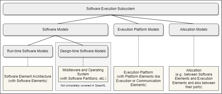
When a software execution component is refined on the next granularity layer as subsystem, which is why we conceptually speak of it as software execution subsystem, a set of models can be used to describe it. This section provides an overview of possible models and their relations. The term “execution” was added to its name, because it is a subsystem that not only models the software of the system but also the execution of the software including the hardware that is needed for this. Figure 3 shows how we divide the software execution subsystem. As part of the software execution subsystem, the execution platform models represent everything that is needed to execute the software of the system. Its main model is the execution platform, which describes a hardware topology of software execution subsystems in terms of execution as well as communication resources. Another part of the software execution subsystem are the software models representing the pure software part of the system. The software models have both dynamic parts, represented by dedicated run-time software models like software element architectures, as well as static parts, namely design-time software models, like middlewares and operating systems. Relations between software architecture and execution platform describe potential allocations of software artifacts to hardware computing or just execution resources.
In SpesML, a software execution component is a container for all model elements of the corresponding software execution subsystem concept and can contain software element architectures (for the run-time software), execution platforms (for the execution hardware topology) and allocations between them. Model elements for the design-time software, like partitions, were not realized in the tool implementation of SpesML. In the following sections, we describe these models in more detail.
Run-time Software Models
Run-time software models represent the dynamic part of the software models in a software execution subsystem. For instance, run-time software can be described by a set of (executable) software elements (e.g., an AutoSAR runnable), which processes information from its inputs to its outputs, and a bus message catalogue, which contains all messages representing the technical dataflow between these software elements. In SpesML, we use a software element architecture, which is part of a software execution subsystem, to model the structure of such software elements, which can communicate via messages:
-
Software Element: Software elements are entities of the technical software architecture to which subcomponents of the logical architecture are mapped. The mapping between logical components, which contain logical subcomponents for software, and software execution components, which contain software elements, is 1:1. The mapping of software-related logical subcomponent to software elements is n:m, although we are recommending again a 1:1 mapping or at least a 1:n mapping for logical subcomponents:software elements. A software element defines how to process (possible) incoming information and create (possible) outgoing information. Messages containing information are received and/or sent by interfaces of these software elements. The software elements will be deployed onto the execution units of an execution platform, which we explain in a separate section.
-
Message: Software element interfaces can be connected to model an information flow between software elements via messages. An interface input can only be connected to exactly one interface output of the same message type. An interface output can be connected to multiple interface inputs of the same message type. Messages contain information that is sent between software elements to process it there. In SpesML, we are using technical interfaces to define such interfaces and specify the messages that can be sent through them. Following the Universal Interface Model, each technical interface can have multiple channels. Each channel has a type that defines which type of information can be sent via the channel (and the interface). Note that we do not explicitly model the behavior of interfaces. The same technical interfaces are also used as connection possibility between all other technical elements besides software elements as described previously.
Software elements can have properties that are useful for further development steps like deployment optimization. As demonstration, we introduced in SpesML the software element properties flash memory usage, RAM usage, and needed ASIL safety level. They can easily be expanded and adjusted for other projects as well. If such properties are defined for every software element and if the execution elements have their own corresponding properties (see execution platform models section), it is possible to use solvers to find satisfying deployment allocation solutions.
The following table shows the mapping between the previously describe concepts (software elements, interfaces and channels) and the SysML constructs we used to realize them in SpesML (together with the names in the MagicDraw tool).
| Concept | SysML Construct | Stereotype / Name in SpesML plugin (MagicDraw) | Shown Name (GUI) in SpesML plugin (MagicDraw) |
|---|---|---|---|
| Container for software elements (software element architecture) | Definition: Block, Instance: Part | SpesML Software Element Architecture | Software Element Architecture |
| Software Element | Definition: Block, Instance: Part | SpesML Software Element | Software Element |
| Software Element Message/Interface | Proxy Port | SpesML Technical Interface | Technical Interface |
| Channel | Flow Property | SpesML Channel1 | Channel1 |
1 Inherited from Universal Interface Model
Design-time Software Models
Conceptually, SpesML also supports design-time software models as part of the software models in a software execution subsystem. These models include models representing specific middleware aspects and operating system models and thus are representing the static parts of the software models. For instance, design-time software models comprise of models representing certain middleware aspects, including, for instance, virtualization aspects and potential OS-related models. Software partitions are one example of artifacts that can be described here.
Design-time software models are usually modeled as black-box models that describe the syntax of such software models.
Execution Platform Models
The execution platform enables the description of an execution hardware topology of software execution subsystems. We call it execution platform, because it mostly represents execution units and we want to clearly distinguish this architecture from a more general hardware architecture that could imply containing, e.g., mechanical components. The previously described software element architectures of the run-time software models cannot model where their software elements are executed. Therefore, execution platforms are needed to specify possible hardware resources for software execution to know in combination with the deployment allocations where the software can and will be executed. The most prominent hardware components hereby are execution units like Electrical Control Units (ECUs) that can execute software elements. However, also technical communication units such as bus systems are highly relevant for the software execution in distributed technical architectures. Therefore, execution platforms can contain execution as well communication elements to represent these two entity types. Although we were focused on these two types for the SpesML project, the metamodel is easily expandable with further types, like e.g., external memory or watchdogs. Therefore, we are talking in general of physical elements when describing the content of execution platforms, and execution as well as communication elements are more specific types among them (see Figure 1).
For actually gaining an added value for systems engineering, an important aspect is to capture more than the structure of the hardware topology alone. The specification of relevant attributes of all technical entities is the key to enable verification and analysis of the technical architecture. For execution elements, this might entail to capture the available memory and computational power. For communication elements, the usual technical aspects are bandwidth, real time capabilities and similar quality of service attributes. As a demonstration within the SpesML project, we have added flash memory capacity, RAM capacity, and guaranteed ASIL safety level as possible properties to execution elements. They correspond to the example properties of software elements, which we introduced earlier. Again, these properties can easily be expanded and adjusted to fit any other project environment. All of these entities and attributes are finally relevant for the allocation models described in the next section.
The connection between physical elements of an execution platform can be modeled via the generic technical interface. Actuators and sensors are often modeled outside the execution platform as part of mechatronic components, but it might be needed that they are connected to some of the internal elements of an execution platform like execution elements. This is why execution platforms and their contained elements can also be connected to other technical components, again via the generic technical interface.
The following table shows the mapping between the previously describe concepts (execution platform, execution and communication elements) and the SysML constructs we used to realize them in SpesML (together with the names in the MagicDraw tool).
| Concept | SysML Element | Stereotype / Name in SpesML plugin (MagicDraw) | Shown Name (GUI) in SpesML plugin (MagicDraw) |
|---|---|---|---|
| Platform/Container for execution and communication units | Definition: Block, Instance: Part | (is in our implementation identical with the software execution component) | (is in our implementation identical with the software execution component) |
| Execution Unit (e.g., ECU) | Definition: Block, Instance: Part | SpesML Execution Element | Execution Element |
| Communication Unit (e.g., CAN bus) | Definition: Block, Instance: Part | SpesML Communication Element | Communication Element |
| Communication Message/Interface | Proxy Port | SpesML Technical Interface | Technical Interface |
Allocation Models
A software allocation model realizes a mapping of software elements from the software element architecture to execution elements of the execution platform. Thereby, it is an integrated platform specific solution model for the software execution subsystem. Such an allocation is necessary to identify the respective execution (and communication) resources for given software architecture artifacts, e.g., an allocation of a set of software elements to certain execution elements to describe the software deployment. This allocation enables further system engineering activities, e.g., scheduling analysis software elements. Finding an optimal or at least suitable deployment allocation can be done via, e.g., SAT solvers, like shown in AutoFOCUS 3. The basis for this is given by the properties that can be set for all software elements and physical elements of execution platforms, as mentioned in previous sections. The following example illustrates this. If all software elements have, e.g., a flash memory usage property and all execution elements a flash memory capacity property, it is easy to define a rule that checks for all manual allocations of software elements to execution elements if the sum of flash memory usage across all software elements that are allocated to one execution element is not higher than the flash memory capacity of this specific execution element. Not only can such a rule be used to check manually made allocations but it can also be used in SAT solvers to generate all possible allocation solutions that fulfill all of such allocation rules for, e.g., deployments.
All allocations of software elements to execution elements in the software deployment model must be of cardinality n:1. This means, that each software element can only be deployed to exactly one execution element, while each execution element can execute several (n) software elements.
In SpesML, we not only have one allocation type for the mapping of software elements to execution elements but two. The reason is that SysML has the concept of type definitions (“blocks”) and instances (“parts”). For example, an execution element representing a special ECU needs to be defined once as a “block”, but this “block” can then be instantiated several times in the diagrams as “parts” to model that this special ECU exists several times in the actual system. To support this concept, we have two allocations for software elements to execution elements in SpesML: a software element instance to execution element instance mapping (for allocations between instances) and a software element type to execution element type mapping (for allocations between types).
Furthermore, we are supporting the allocation of software element interfaces to execution element ports. This software element interface to execution element port mapping might be needed to specify which interface of a software element maps to which port of an execution element. It is, e.g., possible that several software element interfaces need to be mapped on the same execution element port, because the latter is a bus port on which the messages of multiple software element interfaces are transported.
When integrating design-time software models, e.g., software partitions, it is important to note that this consequently has an effect on the allocation models as well. Models from the run-time software, e.g., software elements, can conceptually be allocated to models of the design-time software, e.g., software partitions, which in turn will be allocated to execution platform models. This means there are software element to partition component mappings and partition to execution element mappings.
The following table shows the mapping between the previously describe mapping concepts and the SysML constructs we used to realize them in SpesML (together with the names in the MagicDraw tool). Be aware that for these realized matrices in MagicDraw the term “task” was used instead of “software element”. This was only done because of implementation issues, but we still mean with “task” the concept of “software elements”.
| Concept | SysML Element | Stereotype / Name in SpesML plugin (MagicDraw) | Shown Name (GUI) in SpesML plugin (MagicDraw) |
|---|---|---|---|
| Software Element Instance to Execution Element Instance Mapping | Allocation Matrix | SpesML TaskInstanceToExecution Allocation Matrix | SpesML TaskInstanceToExecution Allocation Matrix |
| Software Element Type to Execution Element Type Mapping | Allocation Matrix | SpesML TaskTypeToExecution Allocation Matrix | SpesML TaskTypeToExecution Allocation Matrix |
| Software Element Interface to Execution Element Port Mapping | Allocation Matrix | SpesML PortToExecution Allocation Matrix | SpesML PortToExecution Allocation Matrix |
Specific Well-Formedness Rules
The technical viewpoint incorporates all the general well-formedness rules (WFR) that were introduced for the whole SpesML concept due to, e.g., the Universal Interface Model. In addition, the following rules were identified specifically for the technical viewpoint, mainly due to its deployment allocations and software element tracing:
- WFR-T1: Interface/Port deployment must be aligned with software element to execution element deployment.
- Software element interfaces can only be deployed to ports of execution elements to which the software element as owner of the interface is deployed itself. It is not allowed to deploy interfaces to ports of other execution elements to which the software element(s) have no deployment connection.
- Reason: It does not make sense to separate interfaces and their software elements between different physical elements in the real world.
- WFR-T2: Each software element must be allocated to exactly one execution element.
- In the end, it is not allowed that a software element is without deployment allocation to an execution allocation, and there must also not be a software element that is allocated to two or more execution elements.
- Reason: There needs to be a clear and distinct deployment.
- WFR-T3: Each software element interface must be either connected to another software element interface or allocated to a port of an execution element.
- In the end, it is not allowed that a software element interface is neither connected nor allocated, meaning that it either needs to have a connection to another software element interface or an allocation to an execution element port. It is also not allowed to have it connected to another software element and at the same time allocated to an execution element port that is not connected to a communication or execution element but to a different physical element.
- Reason: It must be clear to what the output of a software element should be forwarded: either to another internal software element or to another physical element.
- WFR-T4: All execution and communication element must be connected to at least one other technical component.
- A communication element must be connected to at least one execution element. An execution element must be connected to at least one other technical component like another execution or communication element or to an external technical component like a sensor or actuator.
- Reason: A stand-alone communication element is useless because it cannot provide any actual communication. A stand-alone execution element that has no connection to other hardware does not make sense for a cyber-physical system since a characteristic of a cyber-physical system is its interaction between software execution and physical world.
- WFR-T5: A logical subcomponent of a logical component that was tagged as software must not be traced to any other element than a software element.
- If a logical component is indicated as software related and it contains further logical subcomponents, these subcomponents can have only traces to software element(s) and not any other technical elements in the technical view.
- Reason: Pure software can only be handled via software elements in the technical view, because only these can and will be deployed and executed.
Based on the introduced examples of properties for software and execution elements, we want to present the following three rules as an example of possible deployment allocation rules (DAR). These rules can easily be expanded and adjusted to fit the needs of any other project.
- DAR-1: Every execution element must have enough memory capacity for all deployed software elements on it.
- If an execution element has software elements that were allocated to it for deployment, the execution element must have a flash memory capacity that is at least as large as the sum of all the flash memory that is needed by these software elements. If this is not the case, the execution element must either get a larger memory capacity or less software elements must be deployed on it.
- Reason: If there is too little memory space on the execution element, not all software elements can be deployed, or some will be overridden. This will likely result in wrong system behavior if the software can be executed at all.
- DAR-2: Every execution element must have enough RAM capacity for all deployed software elements on it.
- If an execution element has software elements that were allocated to it for deployment, the execution element must have a RAM capacity that is at least as large as the sum of all the RAM that is needed by these software elements. If this is not the case, the execution element must either get a larger RAM capacity or less software elements must be deployed on it.
- Reason: If there is too little RAM space on the execution element, not all software elements might get executed correctly and in time. This will likely result in wrong system behavior if the software can be executed at all.
- DAR-3: Every execution element must have an ASIL safety level that is high enough for all deployed software elements on it.
- If an execution element has software elements that were allocated to it for deployment, the execution element must guarantee an ASIL safety level that is at least as high as the highest ASIL safety level of all these software elements. If this is not the case, the execution element must either get certified for a higher ASIL safety level or the software elements that have the too high ASIL safety levels must not be deployed on it.
- Reason: If an ASIL safety level cannot be satisfied by the hardware, it is possible that some needed safety features might fail. This will likely result in wrong system behavior in case of an emergency or safety failure.