Interface Modeling of Physical and Mechanical Systems
The engineering of cyber physical systems (i.e. systems consisting of physical and digital parts) is a very complex task that usually requires extensive expertise in the individual engineering disciplines (mechanical engineering, electrical engineering, computer science). The development of components from these disciplines also requires specific tools and processes. The SPES methodology supports the engineering of such systems up to a certain level of abstraction and allows the integration of specific development processes via the mechanism of granularity layers which will be discussed in more detail in this paper.
We focus on cyber-physical systems (CPSs), which combine software applications and physical capabilities. In such systems, the software components control and monitor the physical components. The SPES methodology was developed especially for such systems.
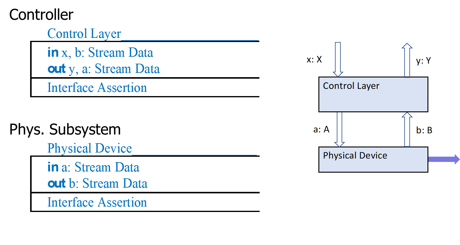
The complete semantic modeling of arbitrary physical systems is an extremely broad topic that requires a lot of domain know-how and cannot be comprehensively addressed within the SpesML project1. Therefore, in SpesML we focus on CPSs where the control of physical subsystems by SW subsystems is in the foreground and choose a correspondingly high interface abstraction for tController_Systemshe modeling of physical parts (see Figure 1).
The way we deal with the behavior of physical parts in SPES varies depending on the model viewpoint.
Functional View
In the functional view only the functional behavior observable at the system border is modeled via data streams. In these models we are at a very high level of abstraction in the interface description. The message types used on the channels are in particular time-discrete. In addition, the means (e.g. by software, or by mechanical components) used to provide the behavior of system functions are not considered. This must be reflected in the definition of the syntactic interface of the system functions (input and output channels and their message types) to remain solution neutral accordingly. The right abstraction is crucial for formal behavior modeling. The functional behavior of the entire system results from the composition of the behavior of the system functions following the FOCUS theory.
Logical View
In the logical architecture of systems (logical view), we decompose a system into components that communicate via data streams. Following our design recommendation (see chapter Tracing between Views and Layers of Granularity), the architecture comprises components that are physical systems and subsystems that correspond to software services. Some of these software services control the physical system using actuators and sensors that convert the digital models into analog (physical) models and vice versa. This control can be very tight or very loose.
In SpesML we choose state machines as abstract discrete models of physical systems2 that are controlled by actuators and sensors. In our particular simple version of theses state machines in each time interval on each input channel or each output channel there is either a message from the set of predefined messages for that channel or the input or output is empty which is represented by a special symbol ε for no message.
As a result, we model the behavior physical components in the logical view by state machines where we describe the particular physical state of the system in some abstraction. Those discrete models are in contrast to control theory where systems are modelled typically by partial differential equations.
Note: First of all, the discrete state machine models the component representing the physical device (physical component) independent from the (digital) control component, which again can be modeled via separate state machine. The interface between the physical and the control component is given by the data streams between the control component and the actuators and sensors of the physical component. Which states of the physical component can be monitored via this interface depends on whether coupling of the software control application is more tight or more loose.
For modelling the control, we use state machines with input and output that define a relation between input and output streams or input and output histories which is the abstract interface behavior of the physical system, as it is seen from the control which just looks at the data streams of signals going through the sensors and actuators. Appling the Universal Interface Model paradigm, the overall behavior of the system can be modeled as a composition of the behaviors of the physical and the control component.
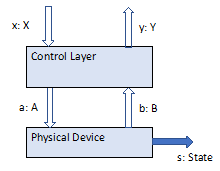
For the discrete model of the physical components we define an attributed state space where each state is represented by a record of state attributes with a given type. The attributes with their types should be selected such that they reflect all relevant aspects of the physical components in the form of the states of their elements and also relevant aspects of the behavior of the physical components.
In our window lifter running example, the state machine might look as follows:
A state consists of two attributes:
mode: {stopped, goin_up, goin_down, alarm}
p: [0:100]
Here p stands for position and represents the position of the window. The mode indicates the actual movement of the window, the position indicates how far the window is closed (p = 100 holds if the window is closed, p = 0 holds if the window is fully open). Alarm models the stopping of the window movement in case something is trapped (pinch guard). The state transitions can be defined by a simple table:
Table 1: State Transitions of the Window lifter with inputs and outputs
| mode | p | input | mode’ | p’ | output |
|---|---|---|---|---|---|
| ≠ alarm | stop | stopped | = p | stopped | |
| stopped | ε | stopped | = p | stopped | |
| goin_down | stopped | close | goin_up | = p | mov_up | |
| goin_up | stopped | open | goin_down | = p | mov_down | |
| goin_up | = 100 | ε | close | stopped | = 100 | closed |
| goin_up | < 100 | ε | close | goin_up | > p | mov_up |
| goin_up | alarm | = p | alarm | ||
| goin_down | = 0 | ε | open | stopped | = 0 | open |
| goin_down | > 0 | ε | open | goin_down | < p | mov_down |
| alarm | > 0 | alarm | < p | alarm | |
| alarm | = 0 | stopped | = 0 | open |
Technical View
Again following our design recommendation, on the abstraction of the TVP, logical sub-components are realized by exactly one technical component whose (syntactic) interface is modeled from an implementation point of view, while in the logical view an abstraction is chosen that allows behavioral modeling of the components (especially from the point of view of the interaction of the software with physical components). The syntactic interface of the technical components are refinements (technical realizations) of the interfaces of the corresponding logical sub-components. Following the argumentation given above for the behavior in the logical view, in SpesML we will not explicitly model the behavior of the technical components.
-
A detailed description of the state transition can be achieved by ordinary differential equations (ODE) in so-called hybrid programs (see A. Platzer: “Lecture Notes on Foundations of Cyber-Physical Systems”, Carnegy Mellon University, 2013). However, the modeling of such differential equations can also be very complex for many physical systems. Therefore, a suitable abstraction of the behavior of the physical part is required. Tools such as Modelica or Matlab Simulink offer possibilities for modeling and simulating such problems. ↩
-
See Broy, M.: „Modelling Cyber-Physical Systems”, tbd, 2022. ↩