 SpesML Plugin - Logical Viewpoint
Overview
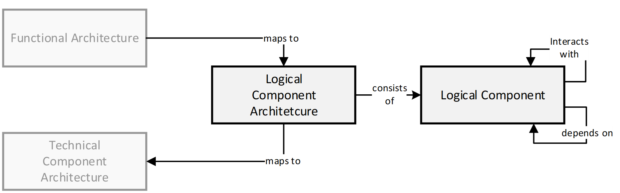
In order to realize the desired functionality that is specified in the models of the functional viewpoint, the system under development is decomposed into a network of communicating logical components. The result is a logical architecture model which is independent of any technological constraints and which can be reused for multiple platforms.
The Logical Components within the Logical Component Architecture provide a syntactic interface and a behavior specified by state automata. To compose the individual logical components to a logical architecture, the interfaces of the components are connected via connectors. Every such connection specifies which output channels will provide values to input channels.
Method
The elements from the functional architecture are mapped onto the components of the logical architecture. In general, this mapping is n:m. We recommend designing the functional white-box models already with the component architecture in mind, to achieve an n:1 mapping of elementary functions onto logical components.
The platform-independent logical components of the Logical Component Architecture will be mapped to technical components of the technical architecture in order to come to a platform-dependent implementation of the component.
The following figure illustrates these relations:
Structure
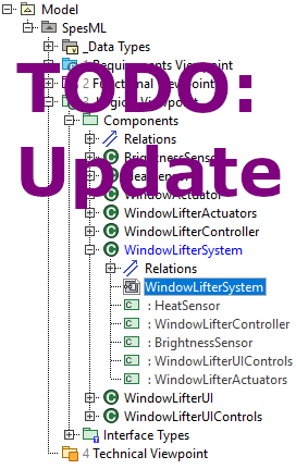
The Logical Architecture is modeled in the Logical Viewpoint folder of a SpesML Project. This diagram can be defined inside any logical (sub-)system (i.e. logical component).
The following figure shows how the logical architecture of an exemplary window lifter system is embedded in the model:
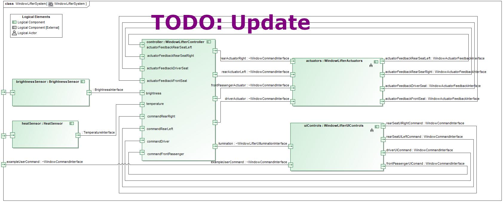
Inside the SpesML Logical Internal Component Diagram the modeler can use all Logical Components to model the actual Logical Component Architecture. The Logical Interfaces of these components can then be connected via Connectors. In the following figure you can see how the logical architecture of the window lifter system is modeled:
How to model
To create the logical architecture of the exemplary Window Lifter above, you can start by following these steps:
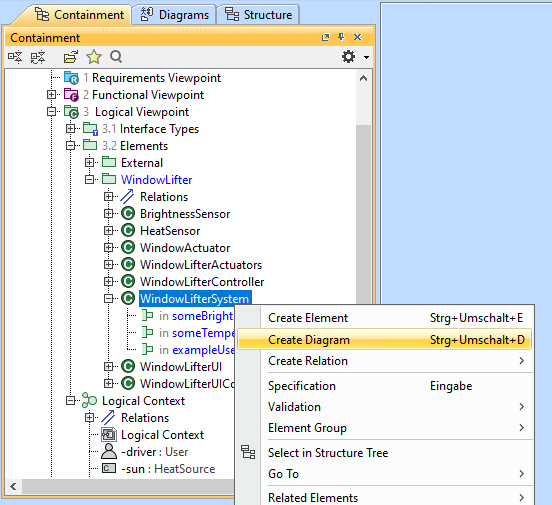
- Navigate to the component in the containment tree, for which you want to model the logical architecture.
-
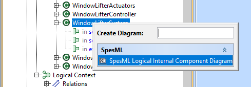
Perform a right-click on this component and select Create Diagram:
-
A dialog will open in which you can select the kind of diagram you want to create. Select SpesML Logical Internal Component Diagram:
-
Another dialog will open that lets you choose, which elements of the selected components you immediately want to display in the new diagram. For our components, this means that we can select which of the interfaces we want to see represented in the diagram. Keep all of them selected and click OK:
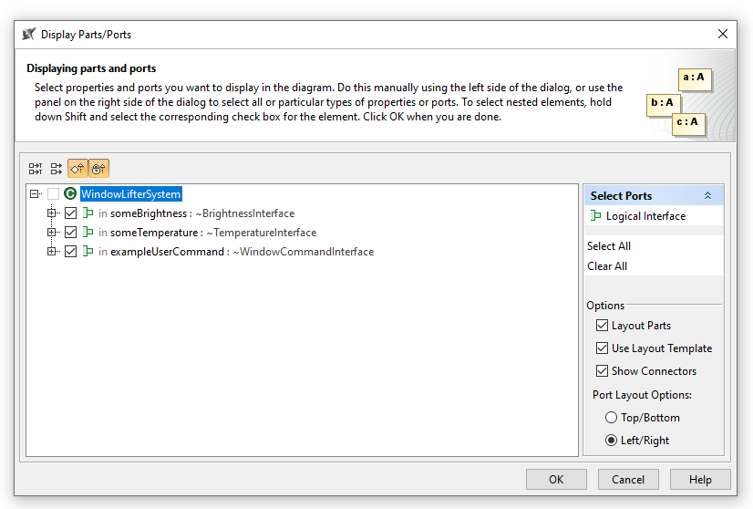
- An editor window with the new diagram will open. It contains only those elements which were already selected in the previous dialog - in our case the three interfaces.
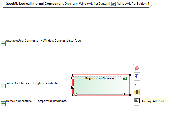
- You can add Parts for the components that you need to model the logical architecture. To do so, drag the components from the containment tree and drop them into the diagram.
-
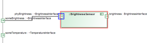
To display the interfaces of the new part, select the part and click on Display all Ports:
-
Connections between interfaces are created in a similar way: Select the port of an interface you want to connect and click on Connector in the menu next to the port:
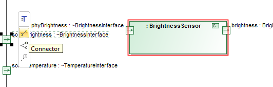
-
Your cursor will become the connector tool with which you can easily navigate to the target port for the connection:
-
Using these mechanisms, you can create the logical architecture of the system:
Elements
Logical Viewpoint
This element is a UML/SysML Package with a dedicated stereotype that allows to define an adequate SpesML model structure and guides users by restricting what elements and diagrams can be created below this package.
 Logical Tracing Package
This element is a UML/SysML Package with a dedicated stereotype that allows to define an adequate SpesML model structure and guides users by restricting what elements and diagrams can be created below this package. This package usually contains only tracing-related relation maps and matrixes.
 Logical Interface Types Package
Insert text here
Logical Test Case Package
Insert text here (TODO: add correct icon)
 Logical Package
Insert text here
 Logical Context
Insert text here
 Logical Actor
Insert text here
 Logical Component
This element is based on a SysML Block with a dedicated stereotype that allows to define where the element. In addition, it restricts that only certain sub-elements can be created below a Logical Component. Logical Components provide a syntactic interface and a behavior specified by state automata. The syntactic interface can be specified by using Logical Interface Types and Channels.
 Logical Component Part
Insert text here
Logical Component with Functions
Insert text here (TODO: add correct icon)
Functional-Logical Adapter
Insert text here (TODO: add correct icon)
Logical Test Case Component
Insert text here (TODO: add correct icon)
 Logical Interface Type
Insert text here
 Logical Interface
Insert text here
 Channel
Insert text here
Diagrams
 SpesML Logical Impact Map
This relation map shows Logical Component and what elements from the Technical Component are tracing to these elements. By default, all Logical Components are shown but it is also possible to drag & drop a single Logical Component to the relation map to show only the particular relationships.
SpesML Logical Tracing Map
This relation map shows Logical Component and to what Requirements or Functional Component these elements are tracing to. By default, all Logical Components are shown but it is also possible to drag & drop a single Logical Component to the relation map to show only the particular relationships.
 SpesML LogicalToFunctional Matrix
This matrix allows to create relationships between elements of the Logical Viewpoint and elements of the Functional Viewpoint.
SpesML LogicalToRequirement Matrix
This matrix allows to create relationships between elements of the Logical Viewpoint and Requirements.
 SpesML Logical Internal Component Diagram
This diagram is based on a UML Composite Structure Diagram/SysML Internal Block Diagram and provides a reduced diagram toolbar related to SpesML. Note that intentionally Logical Component Parts cannot be created using the diagram toolbar. Instead, it is recommended to create these elements by dragging/dropping a Logical Component into the diagram.