Functional Viewpoint
The Functional Viewpoint contains three model types that can be used to describe the desired functionality of a system on a system level (i.e., primarily from the perspective of external actors such as users or external systems).
In the center of the Functional Viewpoint is the concept of system functions. A system function describes a coherent set of interactions between a system and its external actors or external systems. The granularity of a system function is comparable to that of a Use Case. A system with several system functions can be called a multifunctional system. In general, system functions describe system behavior that is largely independent of each other, however, system functions may also influence each other in specific cases. In the Functional Viewpoint, these influences are modeled by so-called mode channels between system functions.
The Functional Viewpoint then consists of three model types:
- Functional Black-box Model: Contains all system functions and structures them in a hierarchy
- Functional White-box Model: Describes the decomposition of one particular system function into a set of related white-box functions
- Mode Model: Describes operational states of the system. These operational states can be referenced in mode channels that describe dependencies between system functions.
In the following, we describe the three model types and how we represent them in SpesML using the universal interface model.
Modeling Elements
Functional Context: The System and its Context in the Functional Viewpoint
Just like all other viewpoints, the functional viewpoint refers to a specific system scope, i.e., there is a clear notion of what is part of the “system” currently under development and what is considered the context of that system. The context described in the functional viewpoint focuses on functions (i.e., chunks of behavior) in the context rather than entities. The system boundary and the system context are specified in the Functional Context. This diagram contains one specific Function that represents the entire System-under-Development (SuD) and additional functions around the SuD that describe functions provided by the context.
The following figure shows the WindowLifterSystem in its functional context
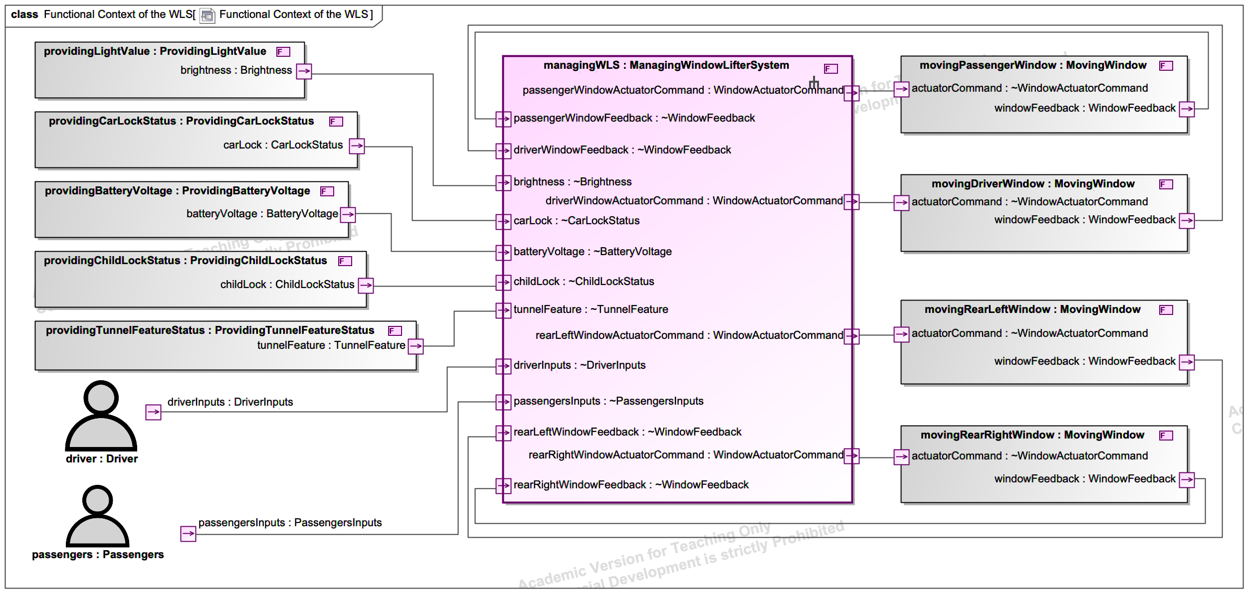
Modeling Rules for the Functional Context
- The functional context must include exactly one system function that represents the SuD.
System Function
A system function describes a coherent set of interactions between a system and its external actors or external systems. For this purpose, it uses the modeling elements of the universal interface model. That means a system function is described by a specific modeling element called Function. Each system function has a syntactic interface defined by a Functional Interface, i.e., a set of input and output ports with associated types.
The following figure shows the system function controllingAllWindows with its associated interface consisting of input and output ports.
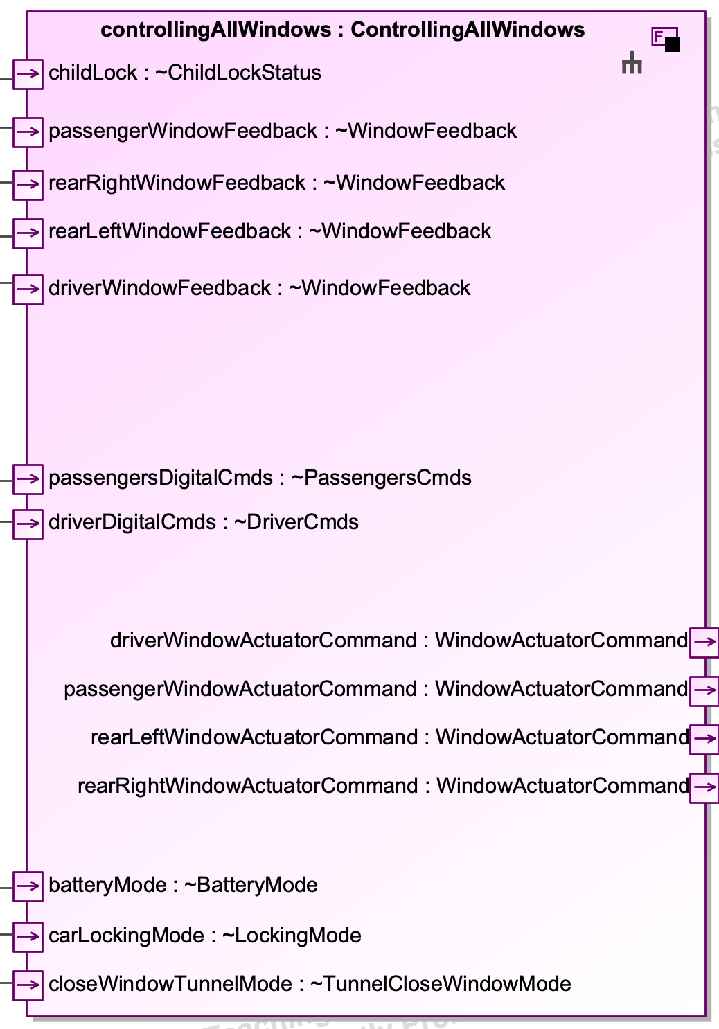
Modeling Rules for System Functions
- System functions must have at least one output port connected to an output port of the overall SuD or at least one input port connected to an input port of the overall SuD.
- Recommendation: A system function models behavior, so the name should begin with a verb (e.g., controlWindows)
System Function Hierarchy
A system can have several system functions. If the number of system functions is small (e.g., less than 10 system functions), we can simply list the system functions and model their interfaces. However, if a system offers a large number and variety of system functions (like an entire car), it may be beneficial to structure the system functions hierarchically with respect to some functional domains. To model this hierarchy, a functional domain can be described as a composition of system functions. Technically, the functional domain is, again, a system function with an interface, which is defined by the composition of the contained system functions. To model this composition, a system function can have parts, which again represent system functions. The ports of the parts can be connected. Such connections between system functions describe functional dependencies between system functions (e.g., a specific state of one system function affects the behavior of another system function). These dependencies should be considered with care since you should specify system functions as independently from each other as possible.
Remember that system functions describe interactions between a system and its external actors or external systems. That means, a decomposition into system functions must not result in internal functions, which have no interface to the context of the system. The system function that represents the root of the system function hierarchy specifies the interface of the entire system from a functional point of view (i.e., by a vocabulary and on a granularity level that is close to the functional system requirements).
The following figure shows the system function hierarchy of the WindowLifter. In this example, the system contains three system functions (controllingAllWindows , collectingInput, and evaluatingSystemModes). There are dependencies between the functions (evaluatingSystemModes and controllingAllWindows) that are used to describe that the window lifter control is influenced by a (low) battery state and by being in a tunnel.
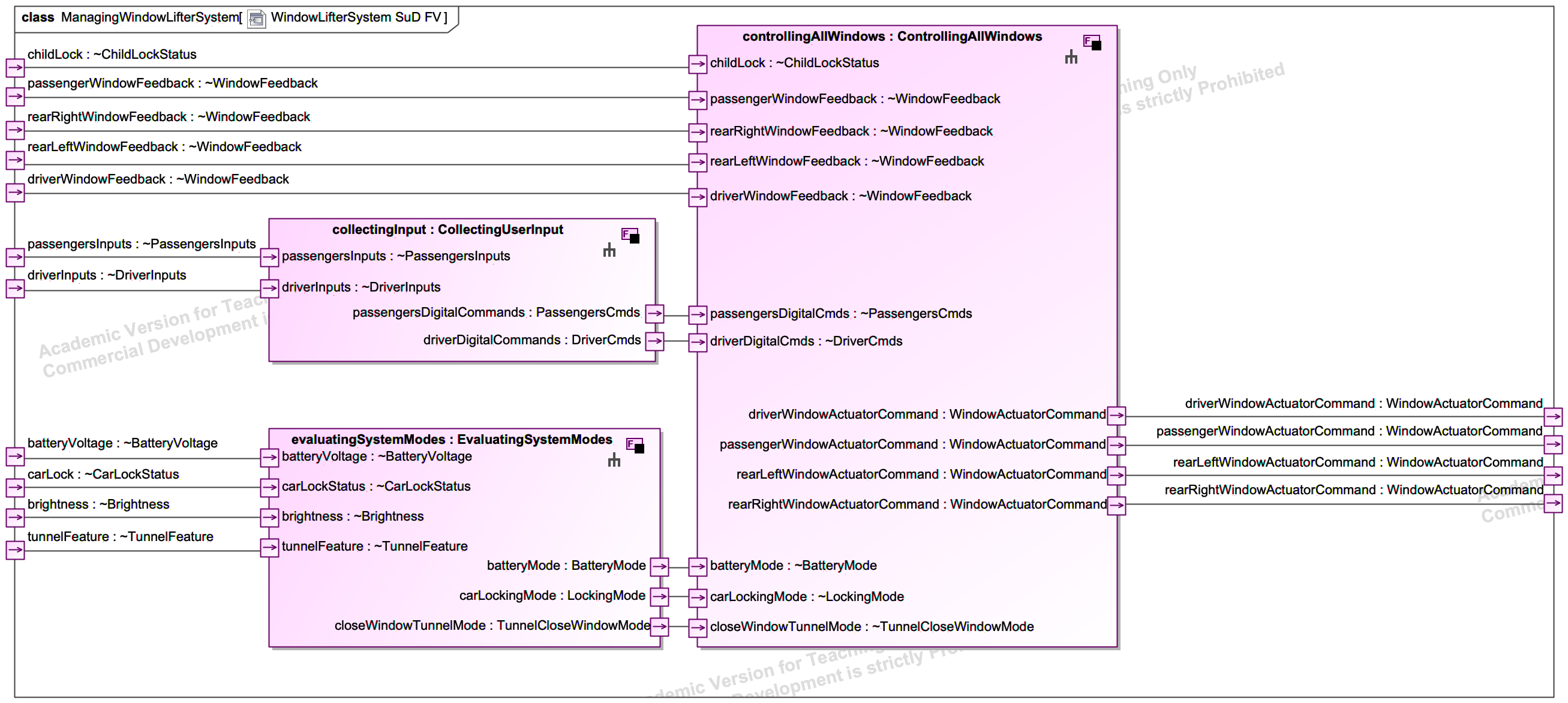
Modeling Rules for System Function Hierarchies
- There exists exactly one root system function, the SuD
White-box Functions
A white-box function describes a unit of behavior that is necessary to realize a system function. For this purpose, it uses the modeling elements of the universal interface model. That means a white-box function is described by a specific modeling element with an associated syntactic interface defined by ports. The behavior of a white-box function can be specified by any type of behavior specification that relates input streams received on the input ports to output streams produced on the output ports (e.g., state machines).
Modeling Rules for White-Box Functions
- Each functional white-box model must be related to exactly one system function.
- Each system function must be related to at most one functional white-box model.
- The interface of a system function (i.e., inputs and outputs) must be reflected in its related functional white-box model, i.e., each input and output port of the system function must also be a free input or output port in the functional white-box model (i.e., a port without any flow property).
- Each white-box function must be related to at most one logical component that implements this white-box function.
Functional White-Box Model of a System Function
A system function is realized by a set of communicating white-box functions (cf. glass-box refinement) that may again be decomposed into smaller white-box functions. To model this hierarchy, a system function is related (via a refinement relation) to exactly one functional white-box model that describes a composition of white-box functions. To model this composition, a white-box function can have parts, which again represent white-box functions. The ports of the parts can be connected. The resulting “chain” of white-box functions for a system function is sometimes also called a causal chain (“Wirkkette”). In contrast to system functions, the majority of white-box functions will only have “internal” ports, i.e., output ports are connected to input ports of other white-box functions. Only a few white-box functions will have input or output ports that are not connected to other white-box functions. These “external” ports must reflect the syntactic interface of the corresponding system function.
Note: An input from a context function can be processed by multiple white-box functions (e.g. if messages from that port need to be processed by multiple white-box functions independently). Output ports, on the other hand, can only be influenced by exactly one white-box function. If multiple white-box functions need to influence one specific port, a coordinating white-box function is needed. Such a coordination function can either be an additional white-box function or the coordination behavior can be added to an existing white-box function.
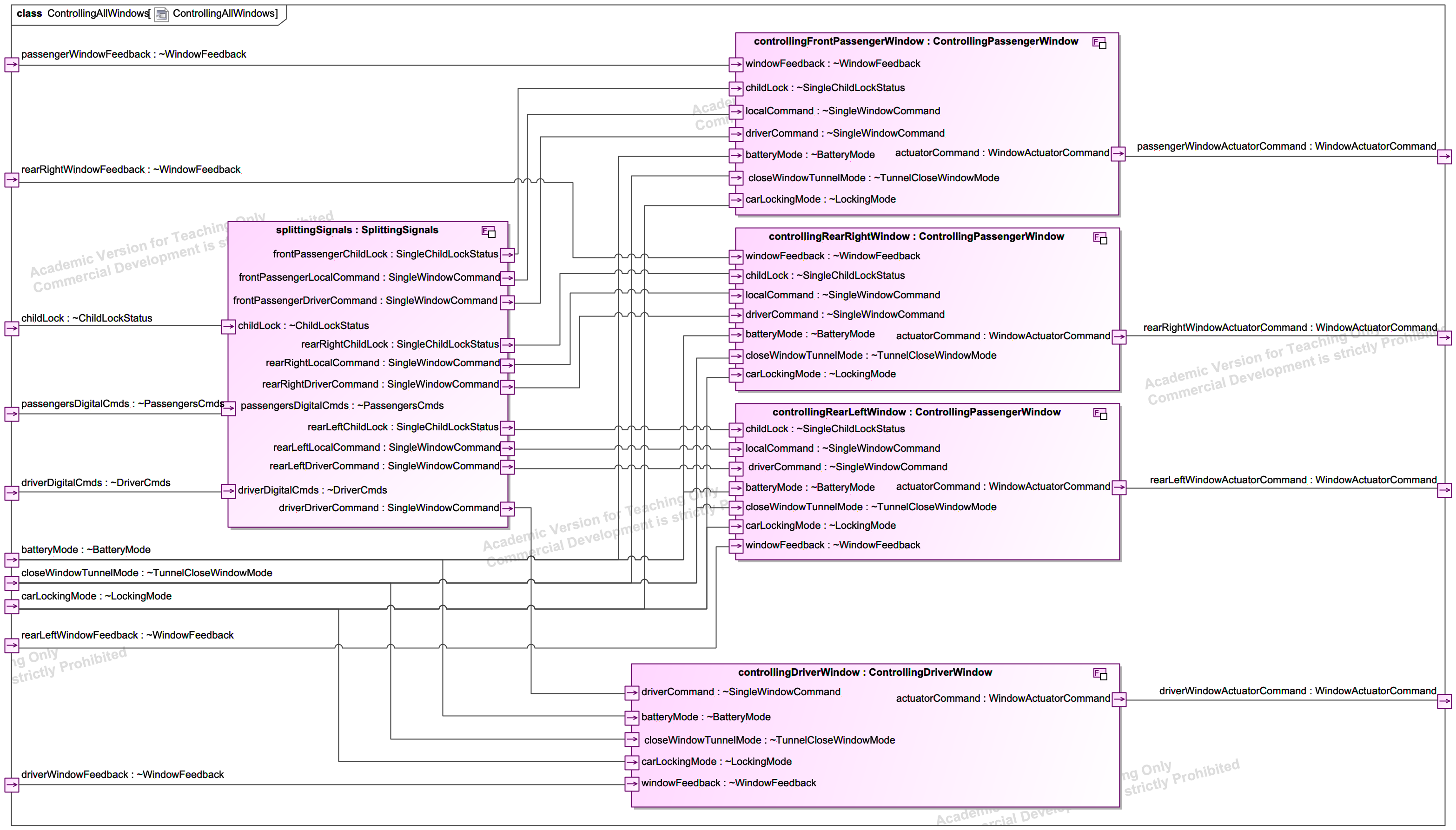
The following figure shows the functional white-box model of the system function controllingAllWindows . It defines five white-box functions that specify the necessary steps to realize the system function.
Mode Model
As described above, system functions can influence the behavior of other system functions. In the functional black-box model, we describe these influences by ports and channels between two system functions. The messages sent over these channels often describe certain operational states (a.k.a. system modes) that influence the behavior of other system functions. Therefore, channels between system functions in the functional black-box model are called mode channels.
In addition to the functional black-box model, we can also describe a mode model that focuses exclusively on the modes and possible transitions between mode values. A mode model is modeled by a state machine where the states represent values that can be sent over a mode channel in the functional black-box model.
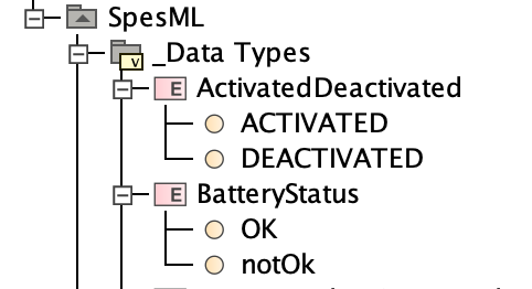
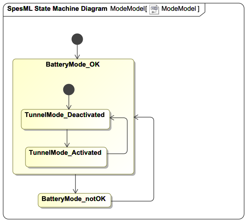
In our example of the Window Lifter, we had two mode channels (closeWindowTunnelMode and batteryMode) between the two system functions evaluatingSystemModes and controllingAllWindows. The port associated with the tunnelWindowClosingMode channel has the type TunnelCloseWindowMode that defines two possible values to be transmitted over this channel (ACTIVATED and DEACTIVATED; see figure below). The port associated with the BatteryMode channel has the type BatteryStatus that defines two possible values to be transmitted over this channel (OK and notOK; see figure below). From this information, we can create a mode model that contains a state for each of the values. In addition to the states, we can also specify transitions between the states to define allowed mode sequences (see figure below). In the example, we specify that only specific mode sequences are allowed to be transmitted over mode channels with the specific mode types. System functions that have an outgoing mode channel with such types must adhere to the allowed mode transitions (e.g., TunnelWindowClosingFunction must not define behavior that sends a sequence like <..., ACTIVATED, DEACTIVATED,...> over the mode channel closeWindowTunnelMode after a message notOK has been sent over the mode channel batteryMode ). Thus, the mode model defines a kind of mode protocol that all functions must adhere to.
Modeling Rules for a Mode Model
- There is at most one mode model per system.
- Each value that can be sent over a mode channel (i.e., a channel between system functions in the functional black-box model) must have a corresponding state in the mode model.
- Transitions in the mode model do not have any guards or actions as they simply define potential sequences of modes.
- A mode model has an initial state but no final state.
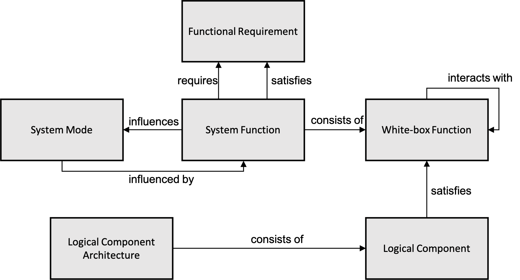
Tracing Relations between Functions and other Elements
Detailed information about trace links between the functional viewpoint and other viewpoints can be found here.
In general, system functions structure and formalize the functional requirements of a system. Thus, system functions can satisfy or require functional requirements.
An engineer may decompose system functions into a set of white-box functions to assign smaller units of functionality to logical components that satisfy the functionality specified by a white-box function.
The following figure illustrates these relations: