Logical Viewpoint
This document describes the basic concepts that will be covered in the logical viewpoint and how they are mapped to SysML elements.
Content:
- Logical Viewpoint
- Logical Viewpoint: Overview
- Logical Components: Central Model Elements of the Logical Viewpoint
- Logical Context: The System and its Context in the Logical Viewpoint
- Interface behavior of Logical Components
- Decomposition of Logical Components
- Tracing Relations between Logical Components and other Elements
- Modeling the Transition to the Technical Viewpoint
Logical Viewpoint: Overview
The logical viewpoint (LVP) describes how the system under development (SuD) can be structured in order to achieve the behavior which is specified in the functional view independent of the technical realization. To do so, the LVP defines how the models of the Logical View (LV) describe the logical system context, the decomposition of the SuD in logical components and sub-components and their respective interface behavior. In the following we describe the basic concepts and models for the LV.
Logical Components: Central Model Elements of the Logical Viewpoint
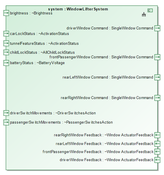
The central modeling concept of the logical viewpoint are the so-called logical components. They strictly follow the universal interface model including syntactic and semantic interface, causality and compositionality. In the SpesML tooling a logical component is represented as a dedicated SysML Block as can be seen in the example in Figure 1:
Logical Context: The System and its Context in the Logical Viewpoint
The logical context models the environment in which the SuD shall operate on a logical level. This can be actors that interact with the SuD or external logical components. One main objective in modeling the logical context is also to specify the logical interface of the SuD to the operational context on a logical (i.e. technology independent) level. Hereby, the logical context model refines the context model of the functional context in the FV. Hereby, usual refinements concern the interfaces and interface types at the system boundary to the system context.
As for the functional and technical view, the logical context defines the scope of what is inside the system boundary and what is outside.
The logical components that shall be outside the system boundary (i.e. in the context) can be specified by a dedicated boolean property with name external per component. In the SpesML SysML-profile, the logical components for the SuD and the element of the context are connected in the logical context diagram as can be seen in Figure 2. 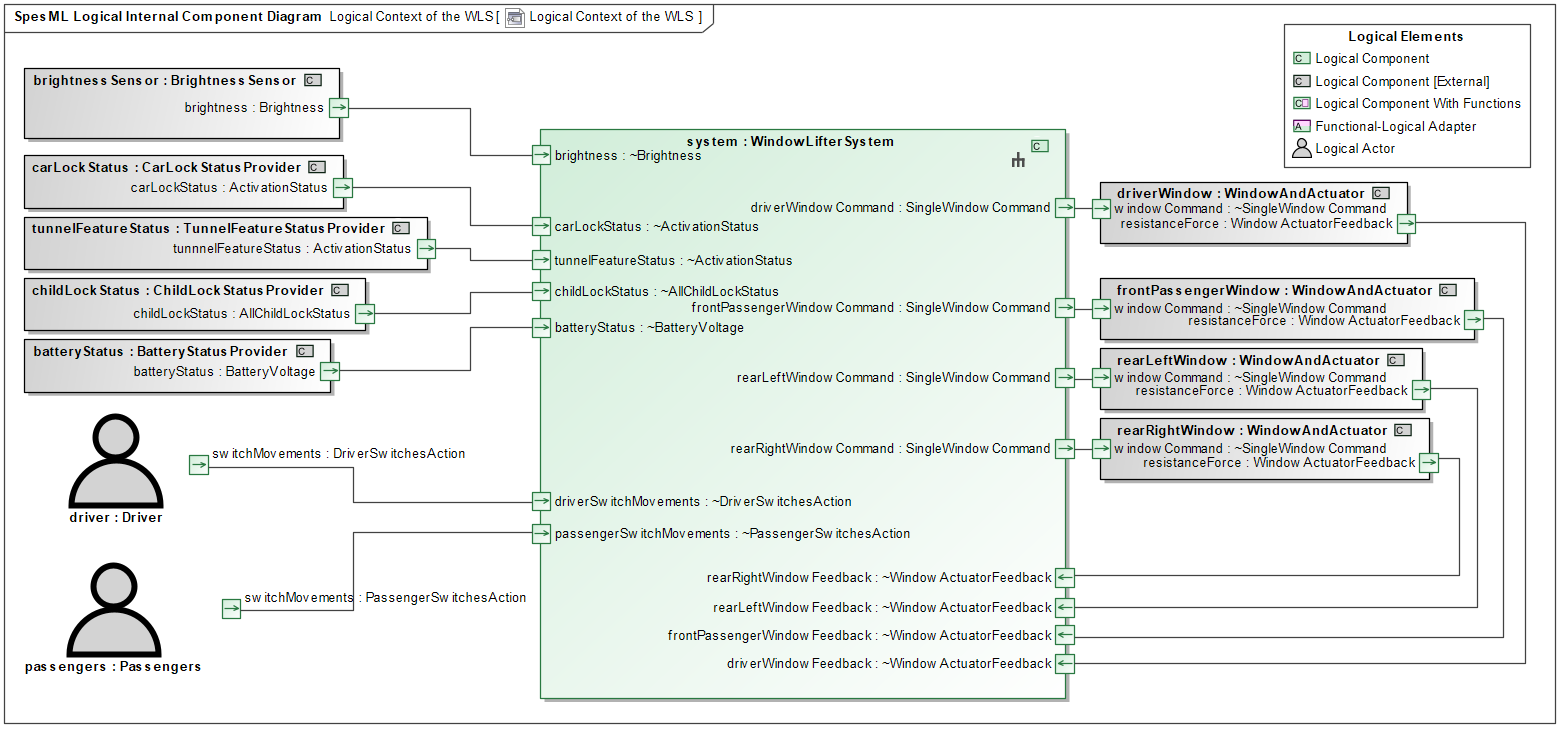
More information on modeling the system context can be found in the context documentation.
Interface Behavior of Logical Components
As already mentioned, also the logical viewpoint is based on the concepts of the universal interface model and it’s mapping to SysML. This means, that interfaces of logical components consist of a syntactical and a semantical interface. The syntactical interfaces of logical components is modeled using logical interfaces which are represented by SysML Proxy Ports. Every such logical interface needs to be assigned a logical interface type which again is defined as a set of channels, represented by SysML Channels. This conceptual metamodel for logical interfaces can be seen in Figures 3: 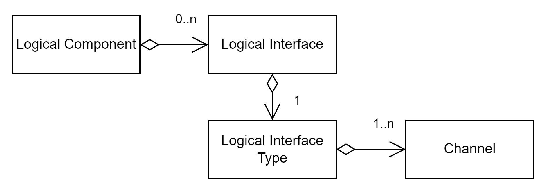
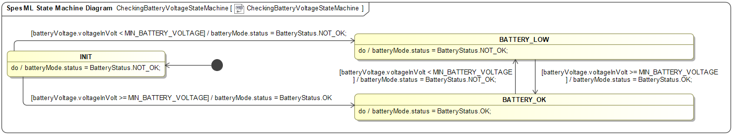
The semantical interface of logical components is modelled by means of state machines that operate based on the component’s input port values and produce the component’s output port values. Hereby, the guards and actions can not only contain comparison and assignment operations, but also use executable functions. More information on SpesML state machines can be found in the respective documentation article. Figure 4 gives an example in the SpesML tool:
Decomposition of Logical Components
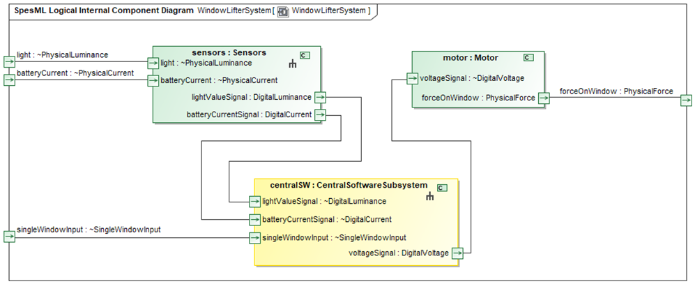
To structure the logical system architecture and to reduce complexity, all logical components can be decomposed into sub-components. This means that the behavior of a decomposed component results from the the composed behavior of the sub-components. In the SpesML SysML-profile and plugin, decomposition is modeled by means of dedicated SysML Internal Block Diagrams (IBDs) in which SysML Parts are instantiated and connected for the subcomponents as can be seen in Figure 5:
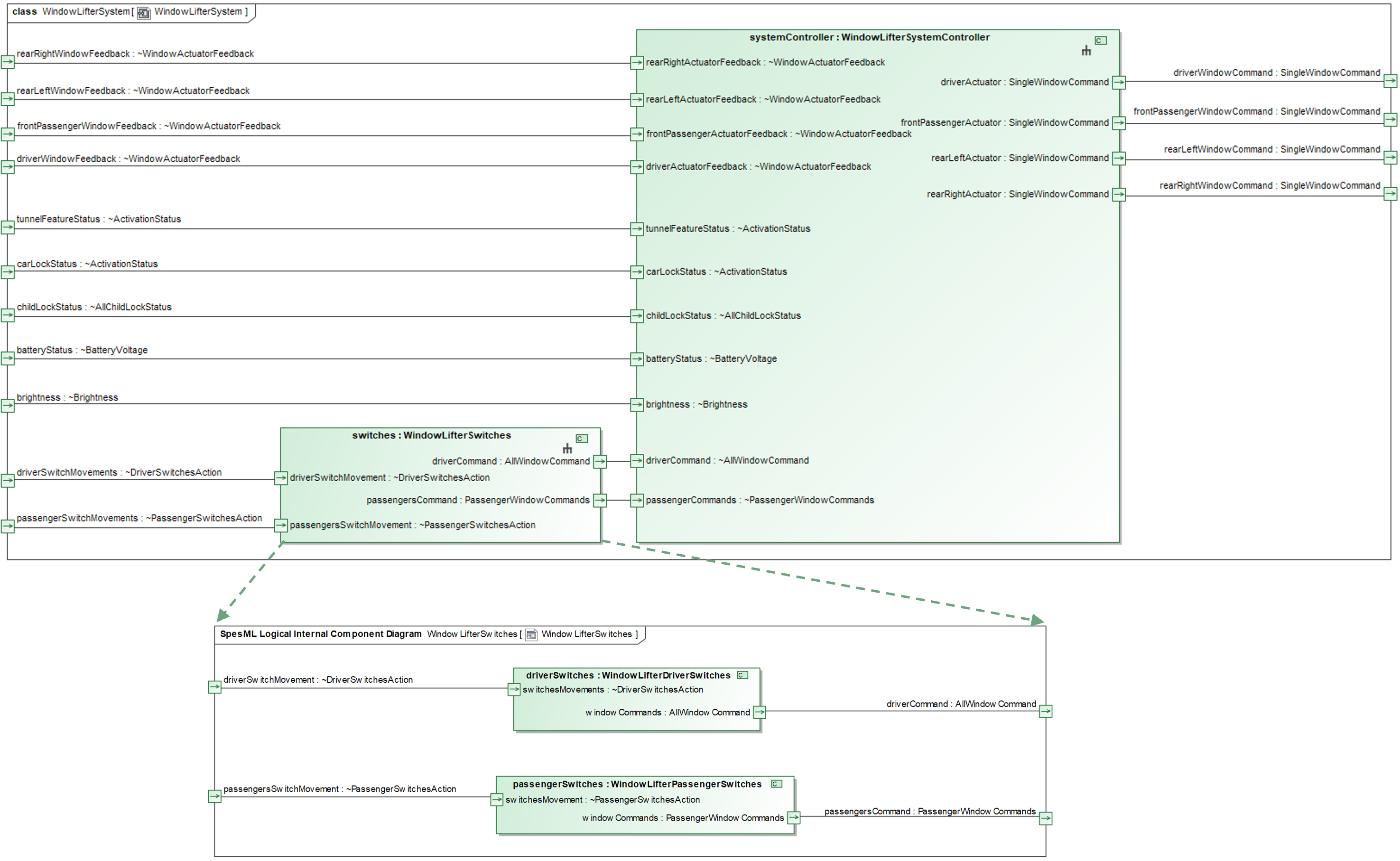
Decomposition of logical components also involves the syntactic and semantic interface of components and sub-components: Here, all inputs of the component need to be connected to an input of a sub-component and all outputs of a component need to be connected to an output of a subcomponent. More detailed information can be found in the documentation of the universal interface model.
Tracing Relations between Logical Components and other Elements
The logical components are traced to the whitebox functions which they realize with a respective tracing matrix. Hereby, we recommend to trace n whitebox-functions of the FV to exactly one logical component.
The technical realization of the logical components will be described by in the technical view. Hereby, we recommend to trace every logical component to exactly one technical component. More detailed information on tracing in SpesML can be found in the documentation of tracing.
Modeling the Transition to the Technical Viewpoint
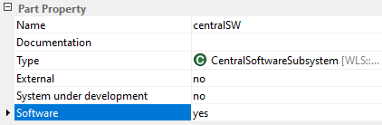
The logical view can also explicitly model certain aspects of the transition from the logical to the technical viewpoint, as is introduced in the technical viewpoint documentation in more detail. In particular the identification of sub-systems in the technical view can be modelled here, by decomposing logical components into different sub-components. Hereby, these logical sub-components can be annotated with the engineering discipline to which they relate in the technical view using a dedicated property. The possible values which are foreseen in SpesML are Software, Mechanical, Electronic and Mechatronic, but in general also other disciplines which are distinguished in the technical view would be feasible. In case this distinct mapping to a single engineering discipline is not possible for a logical component or sub-component, a clear tracing to a technical component of a single engineering discipline would not be possible, either. In all such cases, the SpesML methodology strongly suggests to decompose or regroup the logical architecture such that a clear assignment to engineering disciplines and a clear tracing to the respective technical components is made possible.
Figures 6 and 7 give an example for how to model the transition to the technical view for software aspects: