State Machines
State machines are a means to model the behavior of functions and logical components in the functional and logical viewpoint, respectively (in the following, we only talk about components but mean either functions or logical components). Using state machines, system engineers can model high-level specifications of a system or implementations of low-level system functionality. Accordingly, state machines can provide specifications to a decomposed component or model the behavior of atomic components, i.e., leave nodes in the components composition hierarchy.
States
The states of a state machine define the state space of a component. The behavior of a state machine is defined based on its state space. During execution, at any given time, the state machine is in a single state, which we call its current state. A state machine may change its current state through the execution of a transition.
A state machine consists of at least one state, and each state has a name that is unique within that state machine. Each state can have an entry action, exit action, and do-activity.
Initial State
The state machine’s execution starts in its initial state. It marks the beginning of the modeled system lifecycle.
The initial state does not have a name, nor can it have incoming transitions. Instead, it must have a single transition, which we call the state machine’s initial transition. This transition is unique in that it cannot have a guard, behavior, or trigger and does not trigger the entry action of the target state.
Hierarchical States
States can be nested hierarchically. A state with sub-states is called a hierarchical state and the parent of the sub-state. Hierarchical states can group states and prevent state explosion. Furthermore, hierarchical states can be utilized methodically by first introducing an abstract state and later refining this state into sub-states. Like any other state, a hierarchical state has a unique name and can have an entry action, exit action, and do-activity. Furthermore, a hierarchical state has at least one sub-state and an initial state.
Transitions can have the hierarchical state or one of its sub-states as the source or target. If a state machine enters a hierarchical state, then it enters exactly one of the state’s sub-states. Therefore, a transition that targets a hierarchical state targets its initial state. Suppose a transition targets a state on another hierarchical level. When executing such a transition, the state machine first successively exits all states along the hierarchy to the next common parent of the transition’s source and target state in order. The transition then executes its transition action. Afterward, the state machine successively enters the states along the hierarchy to the transition’s target state in order.
Transitions
A transition leads from a source state to a target state. When a transition executes, the state machine switches from the transition’s source state to the transition’s target state. Furthermore, a transition can have a guard, a trigger, and an action.
A transition is enabled for execution exactly if its source state (or one of its sub-states) is the state machine’s current state and the guard holds. If multiple transitions are enabled for the same trigger at any point in time, then the state machine is nondeterministic.
Trigger
An event triggers a transition’s execution. An event can be a clock signal for timed state machines or a message signal on incoming channels for asynchronous state machines. A clock signal triggers any transition without an explicit trigger. For message signals, the trigger defines the port where message signals trigger the transition.
Guard
A transition’s guard governs the transition’s execution. That is, a transition can only execute if its guard holds. Guards are strongly typed, boolean expressions over value attributes and messages on the incoming channels of the enclosing block.
Behavior
Actions define the behavior of a component or respective state machine in terms of messages sent via outgoing channels. The actions defined in the transition’s effect are executed after any exit action of the source state and before any entry action of the target state. Actions may read and write to value attributes, write to outgoing channels, and read from incoming channels of the enclosing block. Actions can be implemented through statements with strongly typed expressions.
Entry Action
A state can have an entry action that is executed when the state machine enters the respective state. An entry action is performed after the transition action and before the entry action of its child states.
Exit Action
Analog to the entry action, a state can have an exit action that executes when the state machine exits the respective state. An exit action is performed before the transition action and after the exit action of its child states.
Do Activity
A state machine can have a do-activity that describes the continuous behavior of a component in that state. For timed components, the do-activity executes any time the state machine remains in its current state on a clock signal.
Timing Abstractions
Streams on channels may be timed or untimed. Furthermore, components may communicate synchronously or asynchronously. These distinctions have implications for the modeling of component behavior. The SpesML supports these through different timing abstractions. These are timed-synchronous, timed, and untimed.
Timed-Synchronous
For timed-synchronous steams, there is exactly one message at any discrete point in time. The observed output behavior of a component changes only with the clock signal. Timed-synchronous components are synchronized via the clock.
A timed-synchronous state machine models the behavior of a timed-synchronous component. Its transitions may only trigger on clock signals; therefore, one transition at most may execute between two clock signals. As the clock signal is the sole distinct trigger, the trigger may be omitted when modeling transitions of a timed-synchronous state machine. As all timed-synchronous input channels are synchronized, there is exactly one input message at every incoming channel at any point in time. The guard of a transition of a timed-synchronous state machine can therefore reason about message properties on all incoming channels. Furthermore, a timed-synchronous state machine produces exactly one message on every outgoing channel during the execution of a transition.
Timed
For timed streams, multiple messages may exist between two discrete points in time. Therefore, timed components may send multiple messages between two clock signals. Timed components have a synchronized clock but consume and produce messages asynchronously.
A timed state machine models the behavior of a timed component. Its transitions may trigger by message events and clock signals. Both must be explicitly defined when modeling a transition of a timed state machine. As components may consume multiple messages between two clock signals, a timed state machine may execute multiple transitions between two clock signals. Therefore, guards cannot reason about multiple properties of incoming messages in reaction to message signals as messages arrive asynchronously. However, a transition of a timed state machine may or may not produce outgoing messages on arbitrary output channels.
The clock signal is modeled as a special message signal, called a tick, that arrives on all incoming channels. A timed state machine only consumes clock signals once there is a tick on all incoming channels. When executing a transition in response to a clock signal, the timed state machine produces a tick on each outgoing channel.
Untimed
For untimed streams, there is no concrete notion of time. Components may send message signals via an untimed channel at any time. Untimed components consume and produce messages asynchronously.
An untimed state machine models the behavior of an untimed component. Only message signals may trigger its transitions. Guards of a transition can reason about the property of an incoming message in reaction to message signals. The transition untimed state machine may or may not produce outgoing messages on arbitrary output channels.
Enabledness
An event triggers the execution of a transition. However, only enabled transitions can execute. A transition is enabled if
-
the transition’s source state matches or is a parent of the current state,
-
the event necessary for triggering the transition occurred,
-
the transition’s guard, which forms constraints onto properties of the incoming event and the state machine’s current state, holds.
The state machine is nondeterministic if, at any time, multiple transitions are enabled.
How to model
-
Navigate to the function or logical component
-
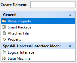
Right-click on this component and select Create Element
-
You may give the state machine a name
-
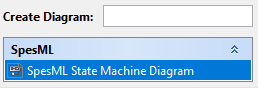
Perform a right-click on this state machine and select Create Diagram
-
A new diagram window will open, showing the diagram palette on the left-hand side and the diagram pane on the right-hand side.
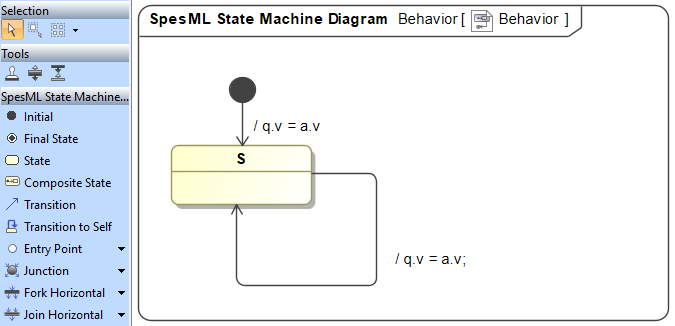
The diagram pane shows the state machine. The diagram palette shows elements to add to the state machine. Select an element via a left click in the diagram palette and add it via a left click in the diagram pane. To delete a state machine element, select it in the diagram pane and press delete.
State
State: Add a state by selecting it in the diagram palette and adding it to the diagram pane. Give the state a name by first left-clicking into the state. The name must be unique within that state machine. The name can consist of numbers or letters of the Latin alphabet but no spaces or other special characters.
Initial State: Add an initial state by selecting it in the diagram palette and adding it to the diagram pane. Also, add a transition from the initial state to another state in the same state hierarchy. The initial state doesn’t need a name.
Hierarchical State: Create a hierarchical state by first creating the parent state as any other state. Select an element (state, transition, initial state) in the diagram palette and left-click a state to add the element as a sub-element of that state.
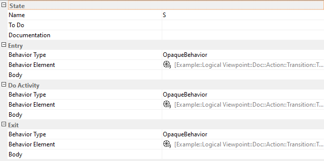
State Specification: Add or modify entry actions, exit actions, or do-activities via the state specification.
-
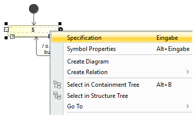
Perform a right-click on the state in the diagram pane to open its menu and select Specification.
-
A new window opens with the state’s specification.
-
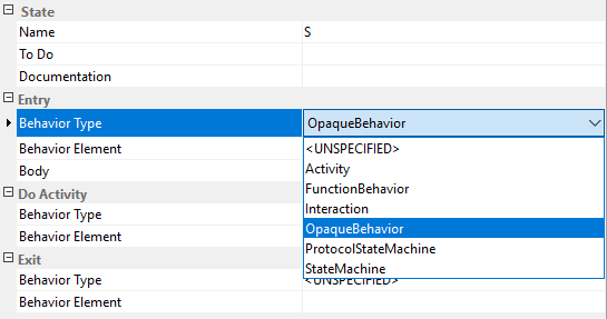
Scroll down to the element in question (entry action, exit action, or do-activity) and select OpaqueBehavior as its Behavior Type.
-
The menu for that element extends, showing additional fields.
-
Add actions as textual statements to the Body of the OpaqueBehavior.
Transition
Transition: A transition is represented in the diagram pane as an arrow from its source to its target state. Add a transition by selecting it in the diagram palette and adding it to the diagram pane. Add a transition to the diagram pane by first pressing left-click onto the source state and then pressing left-click onto the target state.
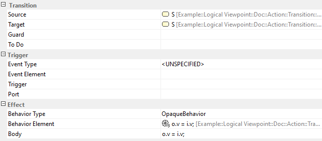
Transition Specification: Add or modify guards, triggers, or transition actions via the transition specification.
-
Perform a right-click on the transition in the diagram pane to open its menu and select Specification.
-
A new window opens with the transition’s specification.
-
Add a textual boolean expression as the transition’s Guard.
-
Select a message event or timing event as the transition’s Event Type. (CURRENTLY UNSUPPORTED)
-
Select OpaqueBehavior as the Behavior Type of the effect.
-
Add actions as textual statements to the Body of the OpaqueBehavior.
Behavior
Entry and exit actions, do-activities, and transition effects are defined via an OpaqueBehavior. Actions are added to the Body of the OpaqueBehavior as textual statements. A semicolon terminates each statement. Statements primarily consist of assignment expressions and inline computations.
Assignment expression may write values to outgoing ports or variables. Furthermore, expressions may read values from incoming channels and variables. However, only ports and variables of the respective component are accessible.
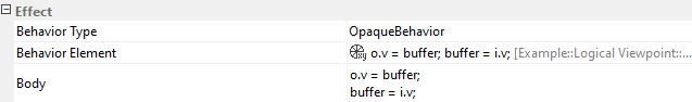
In the above example, the transition writes a buffered value to an outgoing channel and then writes the value on the incoming channel to the buffer. Channels are accessed via a qualified name consisting of the port and channel of the respective interface type. In the above example, o is the name of the outgoing port, and v is the channel’s name. Similarly, i is the name of the incoming port, and v is again the channel’s name. On the other hand, variables can be accessed via their simple name. In the above example, buffer is a variable of the respective component.
Behavior - Executable Functions
To reuse complex expressions, they may be implemented as a set of executable functions which are then included and used in the expressions of an OpaqueBehavior. To use them in the behavior of a state machine, they need to be imported. Imported functions can then be called as described in the executable functions definition.
How to use Executable Functions
To use executable functions in the state machines OpaqueBehavior, one may import them:
-
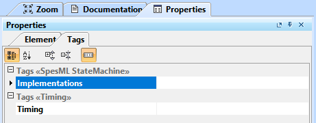
Select the state machine and in its Properties tab go to the Tags tab.
-
Double-click the field right to Implementations to open the dialog to add an executable functions module.
-
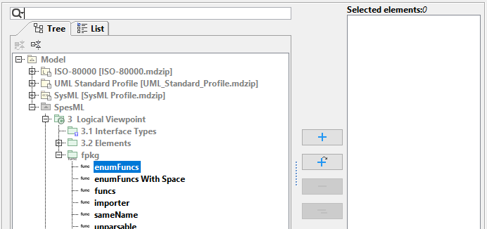
On the dialogs left side select a function module in the containment tree. Add it to the state machine using the plus button. Repeat to add more modules.
-
Confirm the changes made in the dialog using the OK button. The functions defined in the added modules are now available in the state machine.
-
Use the functions (as described in their documentation) in the behavior of the state machine. In the example below, the function switchE is called using the parameter E.e1.

Further Thoughts
-
Non-determinism
-
Unsupported elements
-
Initial state in hierarchical states
-
Sequential composition