Table of Contents
- Layers of Granularity
- Project Structuring
- Challenges
- Potential Solutions
- Recommended Implementation Scenarios for SpesML
- Tracing Concepts for Layers of Granularity
Granularity Layer Transitions
We provide recommended and possible solutions related to tool support for the transition between granularity layers of a system model. The layers of granularity are described in more details here.
Layers of Granularity
As described in Figure 1, the SPES framework shows the distinction between layers of granularity of the system view and associated decomposition relationships. The SPES method can be applied to any chosen granularity layer to model the considered system.
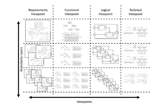
According to Böhm et al. 2021 the layers of granularity help to:
- control the complexity of the system under consideration,
- perform checks on the system at different levels of complexity,
- distribute development tasks,
- reuse individual models several times.
However, implementing the transitions between different granularity layers in a modeling tool like MagicDraw brings certain challenges that need to be overcome. We therefore discuss these challenges and describe potential solutions. Note that while Figure 1 shows four granularity layers, there may be any number of layers, depending on the complexity of the system and how it is decomposed.
Typically, there are two basic approaches for system development, top-down and bottom-up, which eventually can be combined according to the specific use case. More details regarding the concepts of top-down and bottom-up approaches can be found here.
Project Structuring
In tools like MagicDraw, a Project represents the storage of all project-specific data, which can be structured in a number of models. Projects can be stored and managed on a server (Teamwork Cloud), there is an integrated version management, branching capabilities and so on, all working on that project level. Access control (with some exceptions) also mostly works on the project level. These limitations usually imply that you need to know the organizational structures in order to work with a tool like MagicDraw. In other words: the organizational structure will typically influence project setup in MagicDraw to properly deal with version management and access control. It must also be noted that the models of several subsystems will generally be on one level of granularity. Based on these constraints, there are several ways to map granularity layers to MagicDraw projects:
1. All granularity layers in one project: This is the simplest approach: there is only one project and all required granularity layers are included in the same project. The simplest solution would just decompose the components further and further until the required depth is reached. This approach requires no special transition between granularity layers and may work for systems where everything is done by one organizational unit due to the constraints in regards to access rights, version control, etc. If there are multiple organizational units involved or even different companies / suppliers working on a common project this approach is not practical.
2. Dedicated projects for each required granularity layer: This solution has a dedicated project for each granularity layer. This approach may work well for layered organizational structures, i.e. where a particular organizational unit is responsible for a particular granularity layer of the system. Since the responsibility for each subsystem is different, subsystem specific projects need to be created. Generally, the SuD at one granularity layer will provide or get input to the other systems at adjacent layers. As multiple projects are interlinked, the transitions between these projects must be handled.
Challenges
In this section, we look at the challenges that arise if we use option 2 from the Project Structuring, i.e. different part / components of the system are modeled in more than one project. Some of these challenges are strongly linked to the particular modeling tool used (here: MagicDraw) (based on the capabilities of the tool), while others are of a more generic nature.
Challenge 1: Propagating changes between granularity layers
The first challenge to deal with is how to propagate changes from one project to another project. As an example imagine that we need to change an interface on our highest granularity level. This change may impact several projects on the lower granularity levels and therefore we need to find a way to deal with such changes.
Challenge 2: Increasing size / complexity
An additional challenge arises from the increasing size and complexity of the models. Regardless if we do top-down or bottom-up development, we have to deal with all the information contained in the project(s). The more complex the system is, the more information we will have. To illustrate the example imagine using a bottom-up development approach where, starting from the lowest layer, every component is described in full details (i.e. multiple views). Now imagine that hundreds of components are developed in this way, then being integrated over multiple levels to finally form the supersystem.
Challenge 3: Intellectual property protection
This is strongly related to Challenge 2: if all information is freely available to all parties involved, problems with intellectual property protection may arise. This is especially important when dealing with different companies. Imagine a customer-supplier relationship where the customer describes (using models) what he expects from a component and the supplier develops this component. The customer wants to provide the supplier with only the information that is relevant for the particular component. The supplier (if providing models) would not want to provide all internal details to the customer but only the necessary ones.
Potential Solutions
In this section we will have a look at potential solutions to the mentioned challenges. Note that the possible solutions are described in the context of MagicDraw but are also generic enough that they could possibly be implemented in other modeling tools.
Solution 1: Used projects
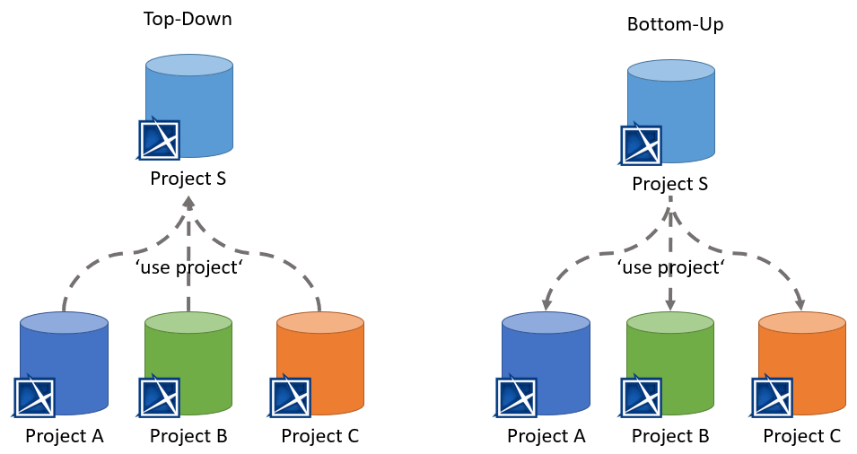
MagicDraw (and most other modeling tools) provides a way to combine multiple projects in order to make the information of one project accessible in another project. In MagicDraw the typical approach would be to ‘use’ an existing project in another one. In case of projects on a Teamwork Cloud server, the option is called ‘Use Server Project…’ but there is a similar option for using locally stored projects. When using the Teamwork Cloud option, MagicDraw will integrate the selected ‘use’, e.g. a selected version of an existing project in read-only mode, into the target project. This allows to access and use all model elements of the used project, however no modifications are possible on these elements. Note that this also restricts relationships (e.g. for tracing purposes) to directed relations where the source cannot be an element from an used project.
Figure 2 below shows an exemplary setup for the top-down and bottom-up scenarios. In the top-down scenario the project S (1st granularity layer) is used by the projects of the 2nd granularity layer. This allows these projects to access all information from project S and establish e.g. trace links between the projects. In the bottom-up scenario project S uses projects A, B and C. This allows to use the model elements provided by these projects to build up system S.
Benefits
- Available out-of-the-box in MagicDraw
- Independent changes on involved models are possible (*1)
Drawbacks
- Diff can be cumbersome (additional information needs to be checked) (*2)
- Manual effort to establish relationships between different projects
- Does not solve challenge 2 (*3)
*1) As an example imagine in a top-down approach that project A has the need to change an interface. Project A could do the change while communicating to Project S. Project S could also make the change to the model, but no project would have to wait for the other model to change.
*2) In order to handle the transition between granularity layers all required projects will be used. This allows to e.g. define dedicated tracing relationships to handle the transition e.g. from the definition of a component on a higher granularity layer to the decomposition of the component on a lower granularity layer. However, it will be difficult to identify and check only the relevant elements among all the information of the used projects.
*3) While MagicDraw provides an option to ‘hide’ packages from a project this typically does not solve anything in regards to Challenge 2. The main reason is that in strongly interconnected models it is not possible to hide meaningful parts without running into issues (unresolved references). In addition, the ‘hide’ option can be used only on a package level, this means that e.g. the internal decomposition of a component will not be hidden, which might run into intellectual protection issues. These constraints will typically result in having to share the complete model.
Solution 2: Create a new ‘input’ project
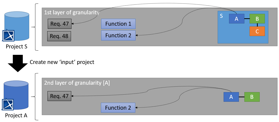
When doing top-down development one could think of automatically creating new projects for dedicated components. In the above example one could think of automatically creating a project for the components A, B and C where each project only contains information relevant for the particular component. For example, when the process is started with the technical component, only the linked (traced) logical components, functions and requirements are given to the new project. In addition, relevant context information might be automatically extracted and also provided. Figure 3 shows a simple example: the process is started for component A and all relevant information (Req. 47 and Function 2) is extracted and put into a new project. In addition, the context information (relationship to component B) is also given. All other information is omitted. Once the project has been created it can be provided to the responsible organization, ready to be further developed in detail.
There described process is not available in the SpesML MagicDraw plugin and would have to be implemented later. There are other modeling tools that have such a process implemented, for example Arcadia/Capella has an add-on called ‘system to subsystem transition’ that works in a similar way. See here for more details.
Benefits
- Solves challenge 2 (for top-down development)
- No relationships between different projects need to be established
Drawbacks
- Issues when changes need to be propagated again (*1)
- Independent changes on involved models are not possible
- Not suited for bottom-up development (*2)
- Diff can be cumbersome due to the way projects are handled
- No implementation in MagicDraw available
*1) When there are changes on the initial granularity layer, the process has to be started again. However creating a new project repeatedly (with new element ids) will result in issues on the next granularity layer when there has been already work done on the project. Either a very cumbersome manual diff & merge has to be performed or the already further developed project would have to be provided to update it.
*2) The described process is well suited for customer-supplier relationships where the customer is not interested in getting a model of the result, instead the customer just wants to describe his expectations to the supplier. Although if a bottom-up development would be technically possible, all non-relevant information would be propagated to the higher granularity layer, which may also create in intellectual protection issues.
Solution 3: Create a new ‘input’ project, then this project is ‘used’
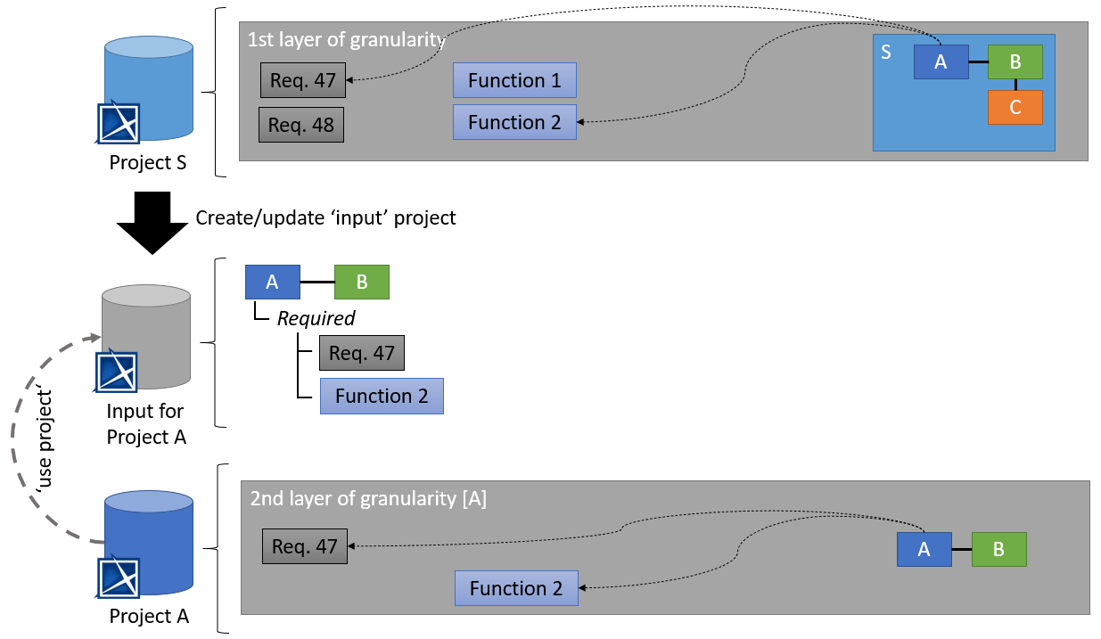
This solution combines solutions 1 and 2. In the first step a dedicated ‘input’ project is created. The goal is not to provide a project that is ready to be used for further development, instead all relevant information is provided as an input for the next granularity layer. The responsible organization then creates its own project that ‘uses’ the input project. While the approach might sound complicated at first, it solves several issues of Solution 2, especially with regard to updates of the input.
Figure 4 shows an example setup. In the first step a dedicated input project is created (or updated) for component A. This project only contains information that is required from the component and must be implemented by the solution provider. In a second step the organization (solution provider) responsible for implementation of component A creates its own dedicated model for project A and ‘uses’ the provided input model. This allows to use the provided model elements and/or establish relationships (e.g. tracing) to these model elements.
Benefits
- Solves challenge 2 (for top-down development)
- Easy diff when the original project is changed
- Independent changes on involved models are possible
- It is possible that multiple organizations provide an ‘input’ for the same component
Drawbacks
- Manual effort to establish relationships between different projects
- Not suited for bottom-up development
- No implementation in MagicDraw available
Solution 4: Create a new ‘blackbox’ project, then this project is ‘used’
This solution is similar to Solution 3 but dedicated for bottom-up development approaches. The goal is to provide project with reduced information (‘blackbox’) that can be provided to be ‘used’ by the next higher granularity layer.
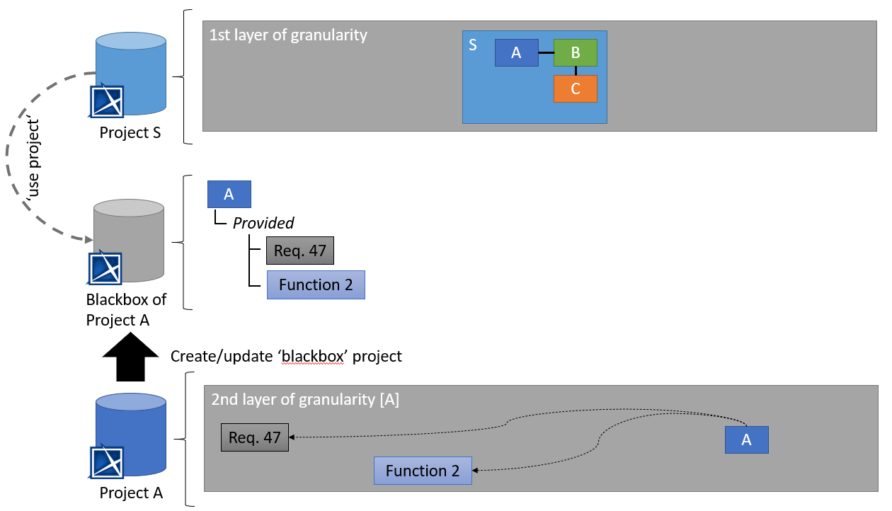
Figure 5 shows an example setup. In the first step a dedicated blackbox project is created (or updated) from component A. This project only contains information that is required to use the component i.e. all internal details are omitted and only those functions are provided that are visible from the outside. In a second step the organization that handles projects S ‘uses’ this blackbox project A. This allows to use the provided model elements and/or establish relationships (e.g. tracing) to these model elements.
Of course the integration and reuse of an existing subsystem (e.g. A) into the supersystem (S) becomes challenging when the interfaces of the subsystem do not completely fit with the supersystem, e.g. we have defined a USB-A interfaces in the subsystem that should be matched with the USB-C defined in the supersystem. In this particular case, when integrating the subsystem to the supersystem, an “adapter” has to be created at supersystem level or at subsystem level. The adapter is a new interface element that serves the interface of the subsystem and provides an implementation solution for the supersystem.
Benefits
- Solves challenge 2 (for bottom-up development)
- Easy diff when the original project is changed
- Independent changes on involved models are possible
- Provided element are ready to be used an can be integrated in the corresponding viewpoints
Drawbacks
- Not suited for top-down development
- No implementation in MagicDraw available
Recommended Implementation Scenarios for SpesML
This section describes two recommended subsystem implementation scenarios in a top-down and a bottom-up approaches using MagicDraw and Teamwork Cloud out-of-the-box. More details regarding the concepts of top-down and bottom-up approaches can be found here.
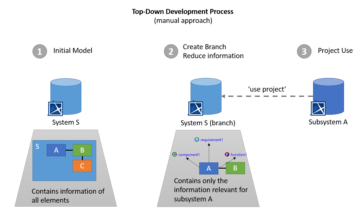
Top-Down approach scenario using MagicDraw
A top-down scenario exists when there is a complex system and one of its subsystems is to be subcontracted, or when responsibility for the subsystems is to be assigned to a domain-specific team in the organization.
A model can be decomposed into separate projects using the project partitioning technique. MagicDraw offers the possibility to partition a model and save the content of a package as a separate project. Projects can be attached to other projects using the Project Usages functionality. In order for this approach to work, it is recommended to create a new “SpesML Model” in the project and move the element (and all dependent elements to that new SpesML Model e.g. tracing relations described in Tracing Concept). Then, the SpesML Model can be exported to a new MagicDraw project.
Another solution to enable the transition from the system to the subsystem in MagicDraw is the use of branches in Teamwork Cloud. Branches can be created from any version of a project and represent a duplicate of that project version, holding all its information. In this case the information required for the subsystem (interfaces and other related modeling elements) can be extracted in a new dedicated project branch. If required, this branch can then be stripped down i.e. all elements that are not required an be deleted. This approach is required for IP Protection / Knowledge Protection. Also note that the Hiding packages utility allows you to hide specified model Packages with elements and used projects. Once specified, which model packages to hide, a new dedicated public branch of the model is created by simply cutting/deleting the hidden parts. The public branch is a particular part of a project (e.g. the system project) that can be reused in another project (e.g. the subsystem project). Figure 6 explains this process.
Recommended approach to provide a project as input for subsystem development:
If the subsystem is developed by an internal organization:
- Grant access to the supersystem project
- The subsystem owner performs Use Server Project to get the input
If the amount of information provided shall be reduced the following steps can be performed:
- Create a branch of the supersystem project
- Delete all information that is not required as input to the subsystem
- Grant access to the project branch
- The subsystem owner performs Use Server Project to attach the supersystem project branch
If the subsystem is developed by an external organization:
- Create a project branch
- Delete all information that should not be exposed
- Export the branch to a local project that can be given to the external organization
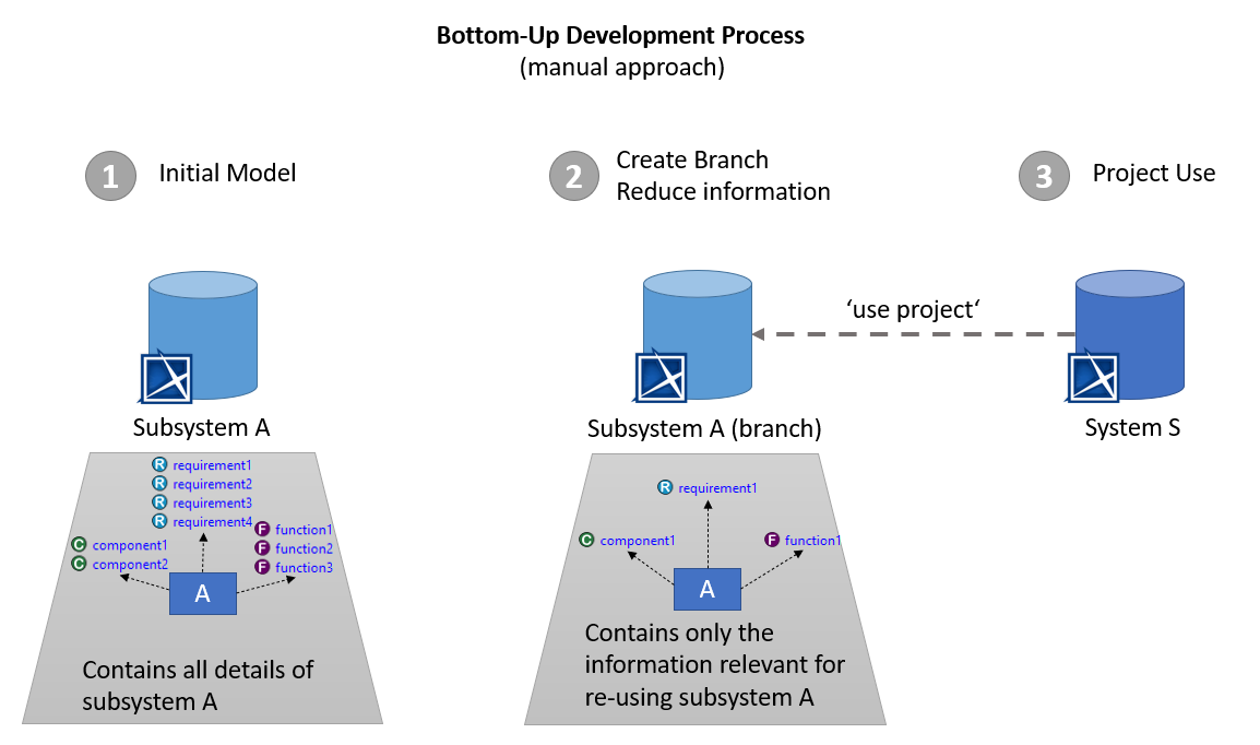
Bottom-Up approach scenario using MagicDraw
A bottom-up scenario occurs an existing subsystem has to be integrated into a supersystem project. Also here we can use both the project usage and the project branching functionalities of MagicDraw applying a similar approach to the top-down scenario.
Using the Project Usage functionality, it is possible to attach a subsystem project to a supersystem project. Shared elements of the used project can then be re-used and integrated as part of the system project. Branches can be created from any version of a project and represent a duplicate of that project version, holding all its information. In this case the information required from the subsystem (interfaces and other related modeling elements) can be extracted in a new dedicated project branch. If required, this branch can then be stripped down i.e. all elements that are not required an be deleted. This approach is required for IP Protection / Knowledge Protection. Also note that the Hiding packages utility allows to hide specified model packages with elements and used projects. Once specified which model packages to hide, a new dedicated public branch of the model is created by simply cutting/deleting the hidden parts. The public branch is a particular part of a project (e.g. the system project) that can be reused in another project (e.g. the subsystem project). Figure 7 explains this process.
Recommended approach to provide subsystem project for integration into a supersystem project:
If the subsystem is provided to an internal organization:
- Grant access to the project
- The supersystem owner performs Use Server Project to attach the subsystem project
If the amount of information provided should be reduced the following steps can be performed:
- Create a branch of the subsystem project
- Delete all information that is not required
- Grant access to the project branch
- The supersystem owner performs Use Server Project to attach the subsystem project branch
If the subsystem is provided to an external organization:
- Create a branch for the subsystem project
- Delete all information that should not be exposed
- Export the branch to a local project that can be given to the external organization
- The external organization can perform Use Local Project to attach the subsystem project
Tracing Concepts for Layers of Granularity
Here we provide descriptions of the SpesML Tracing Concept i.e. how elements from the SpesML Views can be properly traced and related to each other, with respect to the layers of granularity.
Tracing between Layers of Granularity
The structuring of the models in the individual views Figure 1 allows components from the technical view to be viewed as independent systems (subsystems) that can be further developed independently. Each subsystem is treated as an independent SuD. It is important to note that subsystems always have an independent architecture and an associated technical implementation.
Hereby, it is irrelevant which methodology (processes, methods, tools) is used to develop the subsystems. In the SPES methodology all such subsystems of a supersystem are clustered in one layer of granularity. Typically, only a careful selection of the technical components will be processed as subsystems.
As subsystems are derived from components of the technical architecture, there always exists a (trivial) model relation between the subsystem and the respective technical component (due to the construction of the layer of granularity).
Of course, the SPES methodology can also be applied recursively to subsystems (see Subsystems). In the following we will assume that subsystems are also modeled according to the SPES methodology and discuss which additional model relations can be identified.
Tracing Relations Between Systems on Different Layers of Granularity
How models of the architecture of the subsystem and the technical implementation can be derived from the models of the supersystems depends on the nature of the tracing relationships of the models in the supersystem.
The model relationships between the models of the functional view and the logical view or the logical view and the technical view of an SuD are n:m, respectively, in the general case. In such cases, meaningful model tracing relations between the supersystem and the subsystem for the models of the functional or the logical view and model integration of the models of the subsystem into those of the supersystem cannot be identified.
Note: Whether an integration of the subsystem models into the models of the supersystem is required at all, depends on the situation of the concrete development project.
Tracing of Architecture Models Across Layers of Granularity
We always use the paradigm of the universal interface model to integrate a subsystem into the supersystem. In particular, the integration of the subsystem is always done as a black-box based on its syntactic (and semantic) interface.
Following the design recommendations from this document for each subsystem, as well as for the supersystem, we have traces to a unique component in the technical view of the supersystem that represents the subsystem and can be traced back to the corresponding models in the logical architecture of the supersystem. The universal interface concept allows the subsystem model to be integrated into both the logical view models (syntactic and semantic) and the technical view models (syntactic), each as a black-box.
Tracing of the Operational Context Across Layers of Granularity
The logical view contains also models of the operational context. Hereby the operational context of the subsystem is a projection of the context of the supersystem defined as follows:
-
The operational context is always defined with reference to the system being developed. From the definition of a subsystem and given the proposed 1:1 relation between technical and logical components, a subsystem is represented by a component in the logical architecture of the supersystem.
-
The operational context of the subsystem contains all context elements from the supersystem that have a direct channel to the component the subsystem in the logical architecture of the supersystem.
-
Furthermore, the operational context of the subsystem contains all components from the logical architecture of the supersystem that have a channel to in the component representing the subsystem. It should be noted that these context elements are not 1:1 copies of the components of the logical architecture of the supersystem, as their behavior might be additionally influenced by the context of the supersystem. Only the syntactic interfaces of those components are identical.