Subsystems and Layers Of Granularity
Layers of Granularity
In order to provide a way to support re-use and supplier relationships in the models, SPES has defined the concept of granularity layers which allows for the definition of subsystems with a decoupled development process. A layer of granularity Please note, that the concept of granularity layers is different from the concept of model decomposition.
The topmost layer of granularity represents the models of the SuD. As discussed above, the corresponding architecture description contains several architecture views (Functional Architecture, Logical Architecture, Technical Architecture) each decomposing the SuD into sets of architecture elements.
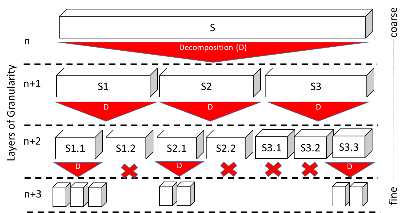
Components of the technical architecture can be selected and engineered as a stand-alone system with an own context1 different from the context of the SuD, using an independent development process. The development process of this stand-alone system may follow any development methodology as long as the resulting system interface model of this stand-alone system adheres to the Universal Interface Model (UIM). In particular, the concept of granularity layers, allows to recursively apply the SPES concepts and viewpoints to selected architecture elements of the technical architetcure which leads to a nesting of architecture descriptions and a hierarchy of granularity layers (see Figure 1)
The models of all selected technical components build the next layer of granularity in the development. Note, as in general only some elements of the technical architecture will be selected, the set of all such components will not form a decomposition of the SuD.
Layers of granularity provide a means to decouple engineering processes and divide them into a number of individual fine-grained engineering processes, complemented by certain activities to support the integration of the various engineering artifacts. This enables, for example, component reuse and the integration of a supplier relation into the engineering process on the level of the technical architecture.
Definition of Subsystems
The structuring of the models for the individual views and the concept of the Universal Interface Model (UIM) make it possible to treat components from the technical view as independent (sub-)systems that can be developed with independent processes, methods and tools and then to integrate these as components back into the higher-level system (super-system). Of course, it is also possible to apply the SPES methodology recursively to subsystems.
We define a layer of granularity as the set of all subsystems identified in the technical view of the super-system. Whether a technical component is further refined as an independent subsystem on the next layer of granularity or is refined only in the viewpoint models of the super-system depends on the circumstances of the specific development project. For example, an independent subsystem will be defined if the development responsibility for the component changes (supplier relationship) or a “suitable” component already exists that is then to be reused.
It is important to note that subsystems always have their independent architecture and their associated technical implementation.
Top Down/Bottom Up
There are two principle approaches to deal with subsystems: The top-down approach starts with modeling the super-system (usually at the first layer of granularity) and recursively defines subsystems at lower layers of granularity. Subsystems in this approach are specified by the models at the super-system level. Model refinement is then performed at the subsystem level based on this specification. The UIM enables seamless re-integration of the subsystem models into the super-system models.
This approach is often found in the development of new systems (greenfield development) and is repeated recursively to create a deeper nesting of granularity layers.
This contrasts with the bottom-up approach, in which the super-system is composed by a set of (possibly already existing) subsystems. This approach is often found in building block approaches, where already available systems are combined to develop the super-system. Hereby, it does not matter whether these subsystems already exist (reuse) or are newly developed. We compose the super-system from a set of (possibly already existing) subsystems. This approach is often found in building block approaches, where already available systems are combined to develop the super-system.
The subsystem must fulfill requirements that originate from a number of sources:
-
A subset or a refinement of the textual requirements of the super-system.
-
Super-system constraints with reference to the subsystem.
-
Additional constraints on the subsystem that arise, for example, from context relationships.
-
Requirements resulting from the interface models of the super-system in the TVP.
In addition, subsystems may have additional requirements as well as their own context or context assumptions, which must be taken into account for their development.
Properties of Sub-SuDs:
-
In general, the next layer of granularity contains the architecture descriptions of several Sub-SuDs, each having its own context and are treated as stand-alone systems.
-
It is immediate consequence from the construction of a layer of granularity that the sub-systems on a granularity layer do not decompose the system (⊕ Si ≠ S), since the composition of Si does not necessarily satisfy all the properties of S.
-
From the construction of the Sub-SuDs we immediately get tracing relations between the architecture models of the SuD and the corresponding models of the associated Sub-SuD.
-
The tracing relations between Sub-SuDs of one level of granularity are always context relationships (i.e. starting from a given subsystem, all Sub-SuDs at the same level are in its context). The modeling is done using the corresponding context models, where the context of a Sub-SuD is formed by the relevant part of the SuD context (mathematical projection of the SuD context onto the Sub-SuD) and all components of the architecture that have a direct operational relationship (e.g. communication channel) to the subsystem.
-
Tracing relation between Sub-SuDs on separate granularity layers can be achieved via tracing relation of their respective parent systems.
-
In the context of these systems are all the other elements of the technical architecture of the SuD. ↩